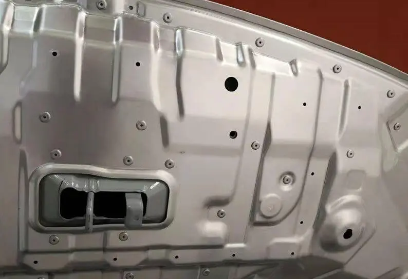
What is the Smallest Allowable Rivet Pitch?
Table of Contents
In structural design and manufacturing, a core issue often arises: what is the smallest allowable rivet pitch. As a connecting component, the pitch design of rivets directly affects the strength and durability of parts. If the pitch is too small, the material will have a reduced effective bearing area due to overly dense holes, and may even lead to tearing or premature failure. If the pitch is too large, the connection area may become loose or crack, thereby affecting the overall structural stability.
Rivet pitch usually refers to the distance between the centers of adjacent rivets in the same row. This parameter, seemingly simple, is closely related to material properties, force distribution, and process standards. This article will combine international standards and manufacturing experience to analyze the design basis, recommended values, and engineering practices of the minimum allowable rivet pitch.
Fundamentals of Rivet Pitch and Related Parameters
In mechanical connections and sheet metal structures, rivets are one of the most common methods of fastening. To ensure the strength and reliability of the structure, several core geometric parameters must be mastered: Pitch (rivet spacing), Edge Distance (margin), Row Spacing (row spacing). These three parameters directly determine the load-bearing capacity, fatigue life and safety of the structure.
1. What is Rivet Pitch?
Pitch refers to the distance between the centers of two adjacent rivets. It is the most fundamental layout parameter. The common recommended range is 2.5D ~ 6D (D represents the diameter of the rivet).
- If the spacing is too small, it may cause the material to crack or have stress concentration.
- If the spacing is too large, there may be bulging of the panels or failure of the connections.

2. Edge Distance - Edge Distance
Edge Distance refers to the distance from the center of the rivet to the edge of the workpiece. It directly affects whether cracks will occur at the edges of the workpiece. The general requirement is ≥ 2D.
- If the edge gap is too small, the rivets are prone to tearing the edges when under force.
- If the edge gap is too large, it wastes materials and is not conducive to lightweighting of the structure.
In actual design, the commonly recommended value is 2D to 2.5D.
3. Row Spacing

“Row Spacing” refers to the distance between adjacent rivet rows. It affects the overall load distribution and fatigue resistance performance. Generally, 2D to 4D is recommended.
- If the spacing is too small, it will cause local weakening of the sheet material.
- If the spacing is too large, it will result in insufficient stiffness in the connection area.
4. Why These Three Parameters Are Critical?
Pitch, Edge Distance, and Row Spacing jointly determine the overall performance of the connection:
- Load-bearing capacity: Appropriate spacing ensures uniform distribution of the load and avoids local overloading.
- Fatigue life: Avoid stress concentration and crack initiation points.
- Structural stability: Prevent warping, bulging or loosening of the plates.
In the aviation and automotive industries, riveted components need to undergo fatigue tests. The data shows that an improper Pitch arrangement can reduce the fatigue life by more than 30%.
5. Design Best Practices
- Always take the diameter D of the rivets as the benchmark and follow the empirical formula.
- Use Pitch ≥ 3D as the safety lower limit.
- The edge clearance should be maintained at 2D ~ 2.5D, avoiding the risk of cracks.
- The pitch should be controlled within 2D ~ 4D, ensuring uniform load distribution.
- For high-strength materials or thin plates, the spacing should be appropriately increased.
Design Basis for Minimum Rivet Pitch

The arrangement of rivets is not merely a geometric issue; it is directly related to the structural strength and safety. The minimum allowable pitch (Pitch) depends on the loading method, the characteristics of the sheet material, the size of the rivets, and relevant standards. The following will be analyzed from four perspectives.
a. Load and Stress Distribution
The rivets may be subjected to shear, tension or fatigue loads during the connection process.
- Shear load: The rivets mainly bear the transverse shear force. If the Pitch is too small at this time, the area between the holes will become too weak and may lead to failure by shearing.
- Tensile load: The edge area of the sheet component is subjected to concentrated tensile stress. If the Pitch is too small, cracks are prone to expand.
- Fatigue load: Under repetitive cyclic stress, the stress concentration around the rivet hole is a key risk point. Studies have shown that when the Pitch is less than 2.5D, the fatigue life may be shortened by more than 40%.
b. Influence of Plate Thickness and Material
- Thick plate: High rigidity, capable of withstanding smaller pitch distances.
- Thin plate: Insufficient rigidity. If the Pitch is too small, it is prone to bulging or cracking.
- Soft materials (aluminum, copper alloys): Require larger pitch distances to avoid fatigue cracks between holes.
- High-strength steel or titanium alloys: Can moderately reduce Pitch, but still need to follow the standard lower limit.
The pitch is usually no less than 3t (where t represents the plate thickness) to prevent the failure of thin plates.
c. Rivet Diameter and Pitch Ratio
International engineering experience is based on the reference of D (diameter of rivets).
- Common recommended minimum value: 2.5D ~ 3D
- Typical safe range: 3D ~ 6D
- The edge distance and pitch distance are usually determined in multiples of D to ensure geometric stability.
For instance, for a 6mm diameter rivet, the minimum value of Pitch should be ≥ 15mm.
The requirements for the minimum Pitch vary slightly among different rivet standards, but the principle remains the same: to avoid stress concentration and ensure fatigue life.
- ASME (American Society of Mechanical Engineers): It is recommended that Pitch be ≥ 3D and the clearance be ≥ 2D.
- ISO (International Organization for Standardization): Most standards adopt a lower limit of Pitch ≥ 3D.
- MIL-STD (U.S. Military Standard): Depending on the material and thickness, typically Pitch ≥ 2.5D is specified.
- FAA (Federal Aviation Administration): Requirements for aerospace structural components are strict. Pitch is generally ≥ 4D, and in fatigue zones, it can even be ≥ 6D.
In safety-sensitive industries (such as aviation and military), the standards are more stringent. It is preferable to sacrifice lightweighting in order to ensure the lifespan.
Practical Design Takeaway
- The minimum Pitch must not be lower than 2.5D, and it is recommended to choose 3D ~ 6D.
- For thin plates and soft materials, a larger Pitch should be selected.
- For fatigue zones or high-stress areas, follow the FAA ≥ 4D or stricter requirements.
- Always consider the three dimensions of D, t, and material together, and avoid considering only one aspect.
Recommended Minimum Rivet Pitch Values
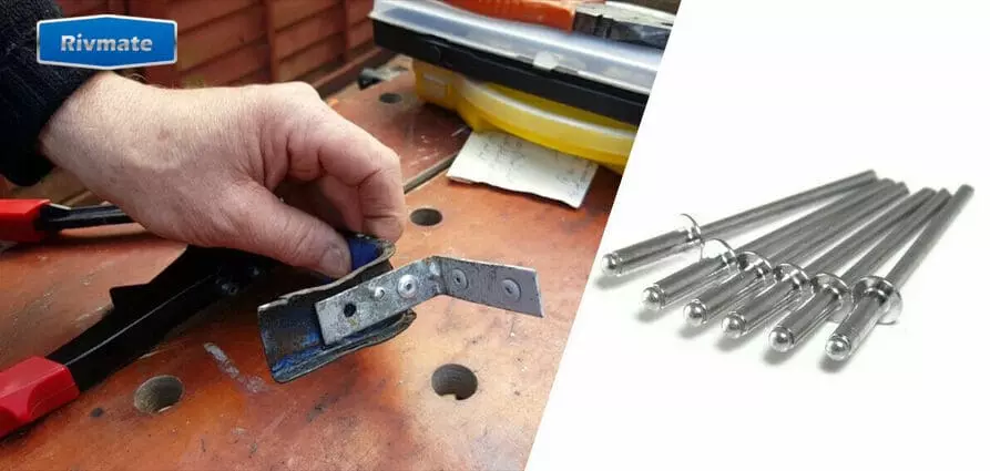
Table: Recommended Values for Minimum Allowable Pitch
| Rivet Diameter (D) | Minimum Pitch (P) | Edge Distance (E) | Row Spacing (R) | Notes |
|---|---|---|---|---|
| 1/8 in (3.2 mm) | 2.5D – 3D | ≥ 2D | ≥ 2.5D | For thin sheet assemblies, avoid cracking |
| 3/16 in (4.8 mm) | 3D | ≥ 2D | ≥ 3D | General structural applications |
| 1/4 in (6.4 mm) | 3D – 3.5D | ≥ 2.5D | ≥ 3D | Suitable for high-strength joints |
| 5/16 in (8.0 mm) | 3.5D – 4D | ≥ 2.5D | ≥ 3.5D | Used in automotive / railway structures |
| 3/8 in (9.5 mm) | 4D | ≥ 3D | ≥ 4D | Heavy-duty structures, bridges |
| > 3/8 in (>9.5 mm) | ≥ 4D – 6D | ≥ 3D | ≥ 4D | Aerospace, marine, and fatigue-critical joints |
Small diameter rivets (≤ 1/8 inch)
Suitable for thin plate assembly. The pitch can be appropriately reduced to 2.5D – 3D, but it must maintain sufficient margins (≥ 2D) to avoid edge tearing.
Medium-diameter rivets (3/16 in to 1/4 in)
This is the most common range, widely used in general structures. It is recommended that the Pitch be set at 3D to 3.5D. At this point, the differences in plate thickness and material have a significant impact on the design, and the choice should be made based on the actual situation.
Bolts with larger diameters (5/16 in to 3/8 in) It is mainly applied in automobiles, railways and heavy structures. Pitch suggests raising the level to 3.5D ~ 4D to ensure uniform stress distribution.
Extra-large diameter rivets (> 3/8 inch) It is commonly found in critical fatigue areas of aerospace and shipbuilding. The minimum Pitch is usually ≥ 4D, and sometimes it needs to reach 6D to meet the strict requirements of FAA or MIL-STD.
Summary of Design Points
- The Pitch must increase along with the D value to prevent crack propagation due to insufficient material between the holes.
- The Edge Distance and Row Spacing are equally crucial. It is recommended to maintain ≥ 2D and ≥ 3D respectively.
- Industry standards vary:
- ASME/ISO: It is recommended that Pitch be ≥ 3D;
- MIL-STD: Allows 2.5D, but requires stricter control of the Edge Distance;
- FAA: In fatigue-sensitive areas, it often requires Pitch to be ≥ 4D, even ≥ 6D.
Minimum Rivet Pitch in Engineering Applications
The minimum Pitch is not a fixed value; it depends on industry requirements and the usage environment. Different rivet application scenarios have different focuses on fatigue life, plate thickness, corrosion, and assembly efficiency. The following summarizes the practical experiences in four typical fields.
① Aerospace Industry
In the aerospace field, riveted structures must withstand high cyclic loads, so fatigue life is the most critical design criterion. To ensure safety, Pitch usually requires a value of at least 4D. In the specifications of FAA and MIL-STD, some key areas even stipulate that Pitch must reach 6D. Taking the aluminum alloy fuselages of Boeing and Airbus as an example, they generally adopt Pitch ranging from 4D to 6D in their designs to reduce crack initiation and delay the occurrence of fatigue failure.
② Marine Engineering
In ship engineering, the selection of Pitch not only needs to consider structural strength, but also needs to take into account corrosion resistance and thick plate welding techniques. If Pitch is too small, stress concentration between holes will occur, and the corrosion expansion speed will accelerate. Therefore, ship design usually adopts 3D as the recommended value, especially in the connection area between decks and bulkheads. Practice has shown that for the bulkhead structure of steel cargo ships, 3D Pitch is the most common and reliable design choice.
The automotive industry emphasizes lightweighting and high-efficiency assembly. Due to the generally thin body panels, the diameter of the rivets used is also smaller, so the Pitch can be appropriately reduced. Generally, non-critical load-bearing areas can adopt a 2.5D Pitch, which can not only ensure strength but also help improve production efficiency.
However, in the chassis and key components involving safety, the Pitch often needs to be increased to above 3D to ensure long-term durability and safety. A typical application is the sheet metal assembly of the vehicle body, and 2.5D Pitch has become a common practice in the industry.
④ Civil and Structural Engineering
In construction and bridge engineering, thick steel plates are commonly used as the main load-bearing components. If the Pitch is too small, it is prone to cause crack propagation in the concentrated force areas, thereby reducing the overall lifespan. Therefore, design specifications generally require that the Pitch in the ordinary areas be no less than 3D, while at the nodes and stress concentration points, the Pitch needs to be increased to 4D or even higher. Taking steel bridges as an example, in the riveted joint areas, a Pitch of ≥ 4D is usually adopted to enhance the fatigue resistance and extend the service life.
Practical Takeaway: Practical Design Points
- Aerospace: Focus on fatigue life → Pitch ≥ 4D (Critical parts ≥ 6D).
- Marine Engineering: Balance thickness and corrosion resistance → Pitch usually takes 3D.
- Automotive Manufacturing: Pursue lightweight and efficiency → Pitch can be as low as 2.5D.
- Building Steel Structures: Pay attention to the force on joints → Pitch is generally ≥ 3D, and critical parts ≥ 4D.
The selection of the minimum Pitch must be based on industry standards and actual working conditions. A Pitch that is too small will reduce the fatigue life, while a Pitch that is too large may lead to material waste and assembly difficulties.
Common Design Errors and Failure Modes in Rivet Pitch
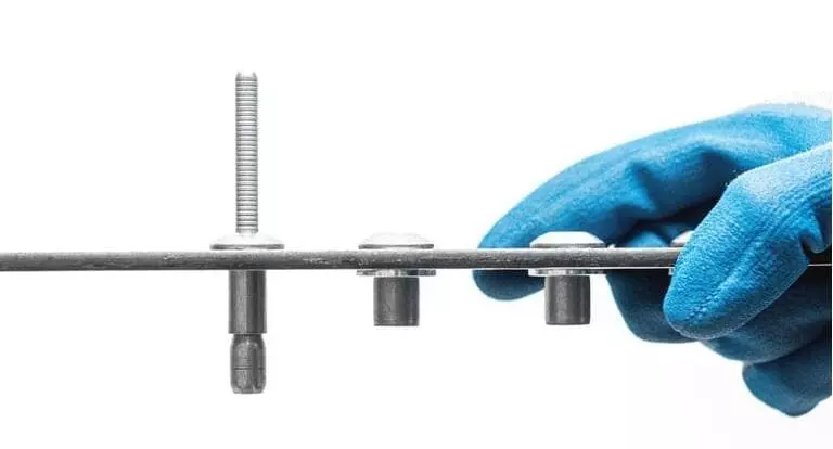
The rationality of the pitch of the rivets directly determines the strength and lifespan of the connection components. Incorrect pitch design can lead to various types of failures, affecting safety and reliability. The following summarizes three common problems and their typical consequences.
Pitch Too Small
Typical failure modes: Plate tearing, inter-pore cracking.
Reason Analysis: When Pitch is less than 2.5D, the amount of material between the holes is insufficient, resulting in significant stress concentration. During tension, cracks are prone to propagate.
Engineering Example: Research shows that when the Pitch is reduced from 3D to 2D, the fatigue life may decrease by more than 40%.
Preventive Measures: Follow the principle of minimum Pitch ≥ 2.5D, and appropriately enlarge it based on the plate thickness and material.
Pitch Too Large
Typical failure modes: Joint opening, structural loosening, fatigue cracks.
Reason Analysis: The excessive pitch causes the load to be unevenly distributed, and the area between the rivets is prone to bulging or warping of the plates.
Engineering Example: In bridges and ships, an excessively large Pitch value can reduce the sealing performance of the joints, accelerating corrosion and fatigue damage.
Preventive Measures: Generally, it should not exceed 6D. For areas with high fatigue, it should be limited to between 3D and 4D.
Uneven Pitch
Typical failure modes: Stress concentration, structural offset, and concentrated fatigue cracks.
Cause Analysis: The pitch distribution is uneven, and some rivets are bearing excessive loads, resulting in excessively high local stress.
Engineering Example: In aircraft maintenance, the non-standard spacing arrangement often leads to local bulging of the fuselage skin.
Preventive Measures: Maintain pitch consistency. If special arrangements are required, finite element analysis (FEA) verification should be conducted.
Rivmate Expert Recommendations for Rivet Pitch Design
In the design of riveting, Pitch not only affects the structural strength but also determines the fatigue life. Rivmate engineering experts suggest considering it from three aspects: plate thickness, rivet diameter, and load type, and using standardized tools to enhance the design efficiency and reliability.
How to Determine Pitch Based on Key Factors
- Plate thickness (t): For thin plates, a larger Pitch (≥ 3t) should be adopted to avoid bulging and cracks; for thick plates, the Pitch can be appropriately reduced.
- Bolt diameter (D): Generally, Pitch should be ≥ 2.5D; the recommended range is 3D to 6D to ensure that the material between the holes has sufficient load-bearing capacity.
- Load type:
- Shear load → A smaller Pitch (≈ 2.5D ~ 3D) is allowed.
- Tension load → It is recommended to be ≥ 3D.
- Fatigue load → It should be ≥ 4D, and for critical parts, it should even be ≥ 6D.
The minimum Pitch should not be considered in isolation; instead, it needs to be evaluated comprehensively in conjunction with t, D, and the load.
Using Rivmate Pitch Verification Table
Rivmate has provided comparison and verification tables based on ASME, ISO, FAA, MIL-STD.
- The table provides the recommended Pitch for different diameter rivets in thin plates, medium-thick plates and thick plates.
- For shear, tension and fatigue conditions, the safety ranges are listed separately.
- Engineers can quickly compare and avoid common design errors.
How Rivmate Products Reduce Pitch Sensitivity
Rivmate’s high consistency rivets achieve this by implementing strict tolerance control and surface treatment, thereby reducing the sensitivity of the Pitch design to failure modes.
- Diameter tolerance control ±0.01 mm → Reduces the deviation between hole diameter and spacing.
- Anti-fatigue surface treatment → Enhances the crack resistance around the holes.
- Batch consistency verification → Ensures the minimization of Pitch deviation after assembly.
The result is: Even when the pitch approaches the design limit, the Rivmate rivets can still maintain a stable fatigue life. This is particularly crucial for industries with high reliability requirements such as automobiles and aviation.
FAQ
Q1: Are the minimum pitches for all types of rivets the same?
No. Different types of rivets (such as open-type, closed-type, and solid rivets) have different minimum Pitch requirements. The minimum Pitch (distance between nail centers) usually depends on the following factors:
- Bolt diameter (D)
- Material strength and thickness
- rivet type and structural method
Take aviation standards as an example, the minimum Pitch of solid rivets is usually set at 2D to 4D. For opening-type rivets used in commercial or industrial applications, the Pitch can be appropriately reduced based on the material’s load-bearing capacity, but it is generally not recommended to be lower than 2D.
Q2: Can the Pitch value be less than 2D?
It is not recommended. A pitch value less than 2D will lead to the following risks:
- Insufficient material spacing, prone to tearing
- Installation tools interfere, insufficient operation space
- Banging pins interfere or deform, affecting connection strength
Unless verified through finite element analysis in the design of extremely small components, general industrial standards typically recommend that Pitch ≥ 2D. For instance, the SAE ASME standards and guidelines from multiple OEMs all stipulate this lower limit.
Q3: How to balance Pitch and Edge Distance in the arrangement of multiple rows of rivets?
The following optimization principles are recommended to be followed:
- Set the margin first, then adjust the Pitch
- The “Edge Distance ≥ 1.5D” is the starting point for conventional design.
- At the edges in the direction of load (pull/ shear), priority should be given to ensuring the margin to prevent material tearing.
- Misalignment design is superior.
- For layouts with more than two rows, “alternating arrangement” is recommended.
- This method can reduce the Pitch requirement and enhance the connection strength.
- Use CAD/CAE for auxiliary analysis
- Before optimizing the layout, it is recommended to conduct interference checks using a 2D model.
- If there is a connection of thin plates, the effects such as plate warping and local yielding need to be evaluated.
Q4: Can Rivmate offer engineering consulting services for pitch optimization?
Sure. Rivmate offers the following professional services:
- Bolts layout optimization suggestions (including Pitch, margin, and arrangement method)
- CAD drawing review and modification suggestions
- Connection strength analysis (can be combined with customer’s FEA report)
- Engineering drawing standardization, in line with international standards (such as NAS, DIN, GB)
For more detailed inquiries, you can contact the Rivmate engineering support team and provide the specific part drawings and connection requirements.
Conclusion

The minimum pitch (spacing) for rivets has no “uniform standard”. It must take into account multiple parameters in actual applications, such as:
- Bolt diameter (D)
- Plate thickness
- Load type (shear or tension)
- Adopted standard (such as GB, DIN, NAS)
A proper setting of Pitch is the foundation for connecting strength, safety and structural lifespan.
An excessively small Pitch can cause material tearing, failure or installation difficulties. An excessively large Pitch may reduce onnection efficiency and increase material costs. When designing the layout of rivets, engineers should fully consider the margin, arrangement method and load path. It is recommended to combine industry standards with actual conditions and use CAD or FEA tools to assist in optimization.
For professional consultation or data support, Rivmate offers services for evaluating and optimizing riveted structures, helping you achieve lightweighting and high reliability of the structure.
Reference

How to Rivet Metal to Wood?
How to Rivet Metal to Woo

What Is Riveting in Metal Work?
What Is Riveting in Metal
What Metal Are Rivets Made Of
What Metal Are Rivets Mad
How to Rivet Metal to Metal
How to Rivet Metal to Met
