Blind Rivets Offer a Number of Advantages over Threaded Bolts
Table of Contents
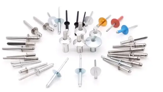
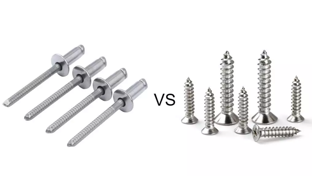
In the modern manufacturing and assembly fields, fasteners are indispensable core components. They determine the strength, reliability and assembly efficiency of structures. With the increasing demands for lightweight and efficient production, engineers constantly compare the pros and cons of different fastening solutions. In this process, the advantages of blind rivets over thread bolts have become the focus of industry attention.
Why do engineers increasingly prefer blind rivets over bolts in more and more scenarios? The answer lies not only in their significant reduction of assembly time but also in their adaptability to single-sided operation environments. According to statistics, the use of blind rivets can increase assembly efficiency by approximately 20% to 30%, while reducing rework rates and inventory complexity. These advantages have made blind rivets gradually become the preferred alternative to bolts in industries characterized by rapid iteration, cost sensitivity, and precise assembly.
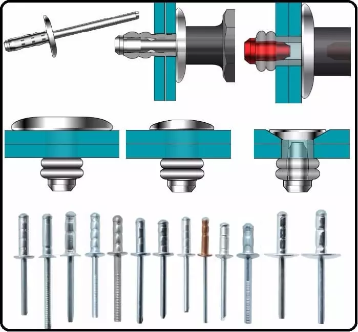
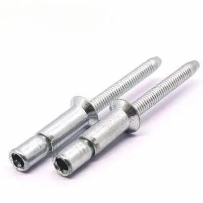
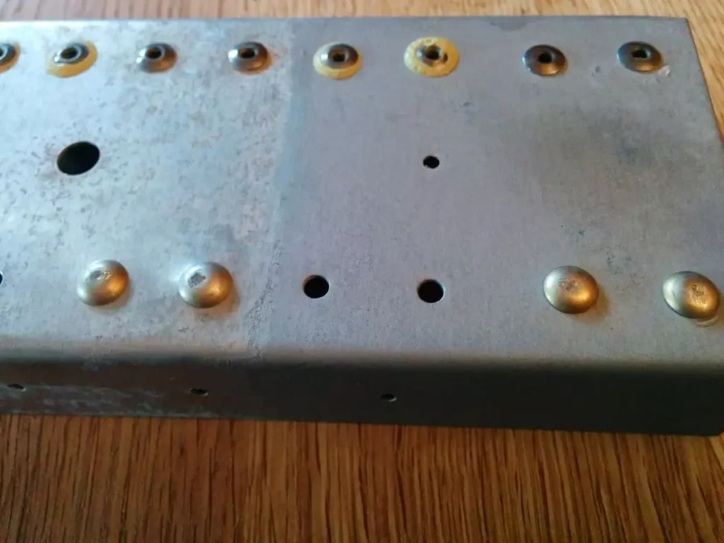
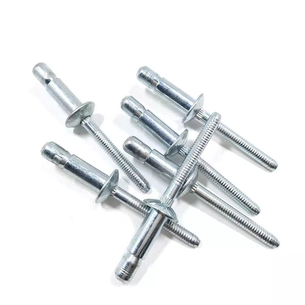
Blind rivets are a type of single-sided mechanical fastener. Unlike bolts, they can secure the object without needing to come into contact with the back side of the workpiece. This characteristic makes them an ideal solution for addressing “unreachable backside” assembly problems.
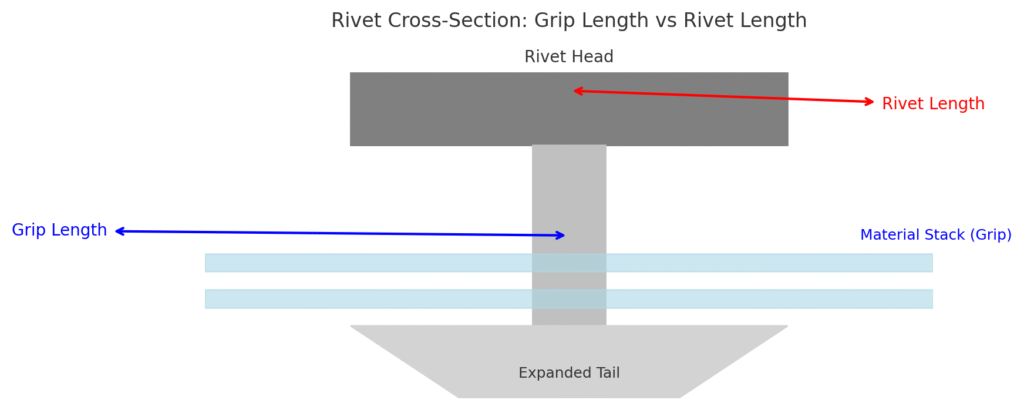
Basic Structure
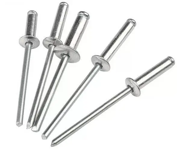
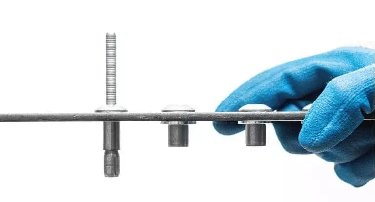
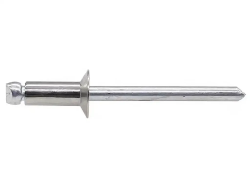
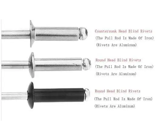
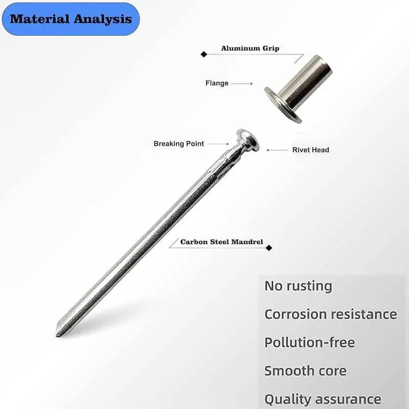
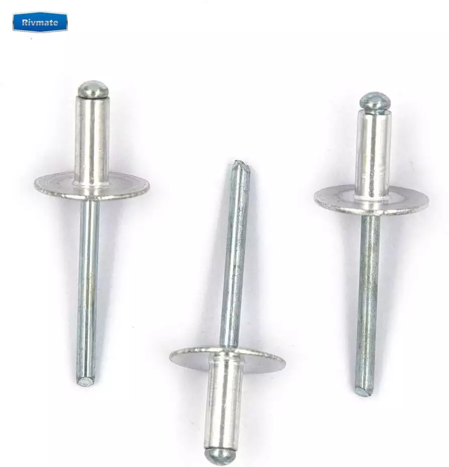
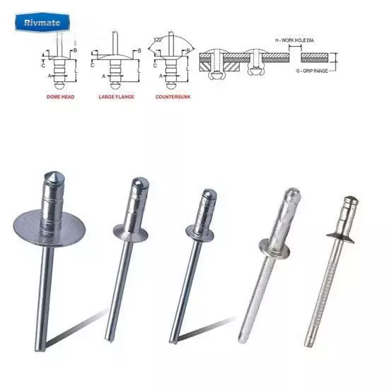
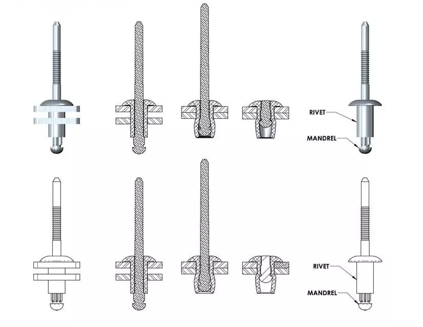
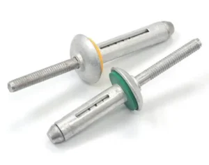
Blind rivets are mainly composed of two parts –
Head: Forms the final locking surface and provides stable clamping force.
Mandrel: Breaks during installation, pushing the head to expand and achieving fastening.
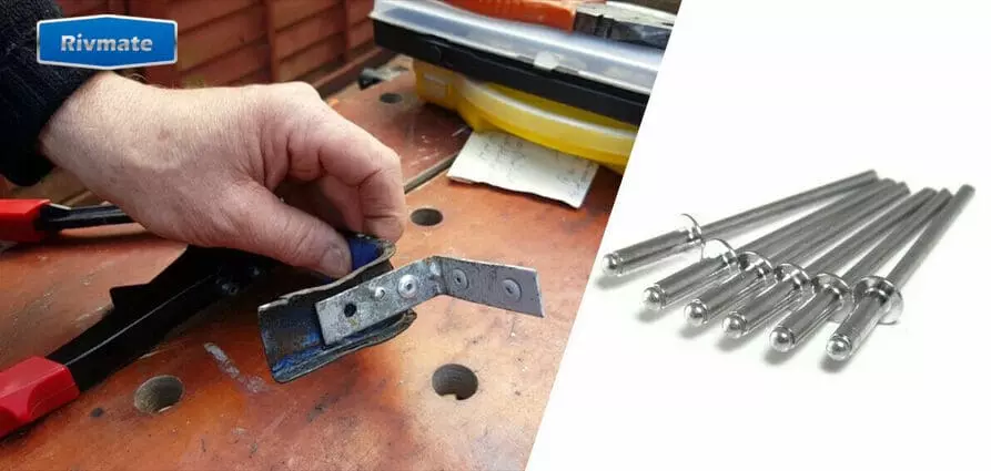
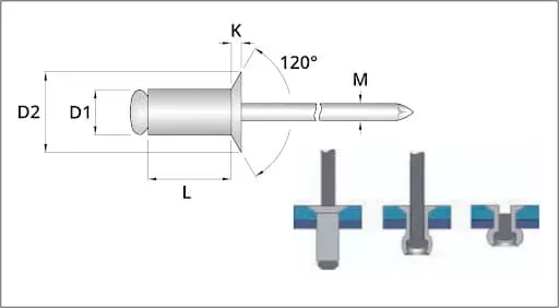
During installation, the operator only needs to use a special pull riveting gun. After inserting the rivet into the workpiece from the front, pull the core shaft to cause the cap to expand. Once the core shaft breaks, a permanent and reliable connection is formed. The entire process is fast, simple, and does not require thread processing.
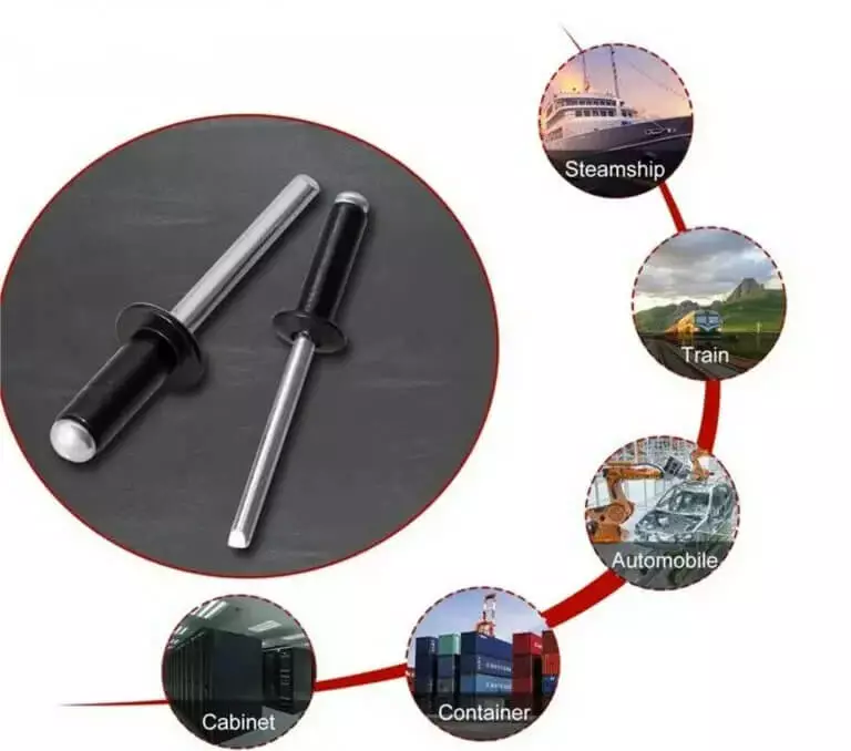
- Aerospace: Assembly of structural components, requiring lightweight and high strength.
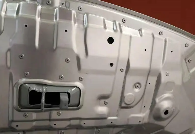
- Automobile manufacturing: Body panels, exhaust systems, etc., often accompanied by vibrations and thermal expansion.
- Construction engineering: Metal curtain walls, steel structure joints, suitable for large-scale installation.
- Electronic enclosures: Suitable for fixing thin sheet metals or plastic parts.
- HVAC systems: Connections of ducts and enclosures, fast installation, suitable for batch construction.
According to market research data, blind rivets account for approximately 12-15% of global fastener applications, and their demand is still steadily increasing. The reasons for this are their high assembly efficiency, low maintenance costs, and strong reliability. This also explains why more and more manufacturers prioritize blind rivets over traditional bolt solutions during the design stage.
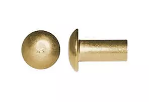
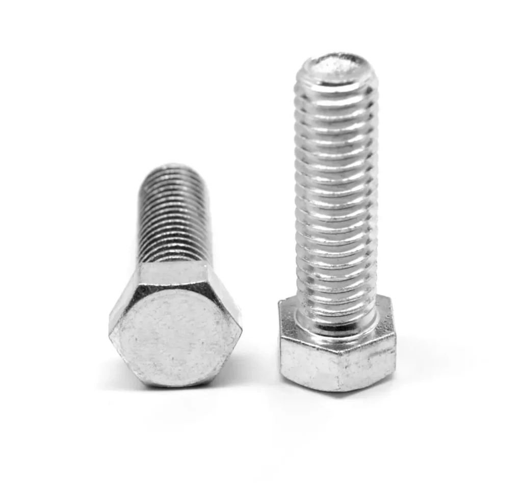
What Are Threaded Bolts?
A bolt is a mechanical fastener that requires two-sided contact. It is usually used in conjunction with a nut and achieves clamping and fixation through the engagement of threads. Compared to blind rivets, it requires both sides of the workpiece to be in contact, and thus requires more installation space.
Main Features
- Removable: The bolt connection can be disassembled and reassembled during subsequent maintenance.
- Reusable: Under conditions where force is permitted, the bolt can be used repeatedly.
- Requires Torque Control: During installation, a tool must be used to apply the appropriate torque to ensure accurate tightening force.
- Reliable Load-bearing: Suitable for high-load and long-term usage scenarios.
Common Application Scenarios:
- Heavy machinery: Such as engineering equipment and mining machinery, must withstand high impacts and continuous loads.
- Structural engineering: In bridges and steel structures, bolts are the key load-bearing components.
- Large-scale assembly: Such as wind power equipment and ship manufacturing, require maintainability and replaceability.
According to industry data, bolts account for over 40% of the global fastener market. This is because they have strong load-bearing capacity and high maintainability. However, they have certain limitations in terms of installation efficiency and space compatibility.
Core Advantages of Blind Rivets over Threaded Bolts
Blind rivets have more advantages in terms of single-sided installation, cycle efficiency, weight reduction, anti-loosening, overall cost and appearance. They are suitable for scenarios where the backside is inaccessible, the production line cycle is tight, and weight reduction is critical.
① Single-Sided Installation
- Just perform the operation on the front side. There is no need to hold the back nut or enter the sealed cavity.
- This is particularly crucial for structures that are difficult to access. Such as closed profiles, boxes, interlayer panels, air ducts and vehicle interior.
- Typical comparison: At the same position, using bolts requires two people (one to tighten on the front side and the other to support on the back side). Blind rivets can be completed by one person.
- Result: Reduces collaborative work at the workstation and rework. Reduces on-site safety risks (fewer entries into narrow spaces).
② Faster Installation Process
- The blind rivets are installed in a single pull riveting operation. No torque wrench, stall control or secondary recheck is required.
- Production line cycle comparison (typical range):
- Blind rivets: 2 – 4 seconds per point (depending on hole preparation and part retrieval and placement).
- Screws + nuts: 8 – 20 seconds per point (part retrieval, hole alignment, gasket placement, hand tightening, torque application, recheck).
- Rough calculation: Each point saves 6 – 16 seconds. Assuming an hourly labor cost of $25, for each product with 100 points, direct labor savings can be $4.2 – $11.1 per piece (excluding quality inspection and rework). This is more significant for large-scale assembly lines.
③ Lightweight Solution
- Under the same clamping force and structural stiffness, the blind rivet assembly is significantly lighter than “screw + nut + washer”.
- Example: Common 4.8 mm aluminum blind rivets are approximately 0.5 – 0.8 g per point; M5×12 carbon steel screws + nuts + washers are approximately 4 – 5 g per point.
- The weight reduction can be 70 – 90% (depending on the material and size).
- For automotive, rail transit and aviation interior applications, there are quantifiable benefits in terms of vehicle/whole-machine energy consumption and range.
④ Excellent Vibration Resistance
- The bolt’s vibration resistance relies on frictional preload. It may loosen under long-term vibration and requires spring washers, nylon locking, thread sealant or secondary inspection.
- The blind rivets become permanently locked after forming. There is no problem of thread slippage.
- In the body panels, exhaust insulation plates, HVAC ducts, and equipment covers, blind riveting connections are more stable and quieter under high-frequency and low-amplitude vibration conditions.
- Fewer parts: The blind rivets are single pieces. The bolt system usually includes bolts, nuts, washers, and even anti-loosening devices.
- Shorter assembly steps: Fewer parts to take, less alignment, no torque tools or calibration required.
- Easier inventory management: Fewer SKUs, lower obsolescence and mismatch risks.
- Rough TCO formula:
- Total cost = (fastener unit price) + (installation time × labor cost) + (quality inspection/retirement) + (inventory holding) + (tool depreciation/calibration).
- Blind rivets often offset the price difference with lower installation and quality inspection costs, and are more cost-effective throughout the entire life cycle.
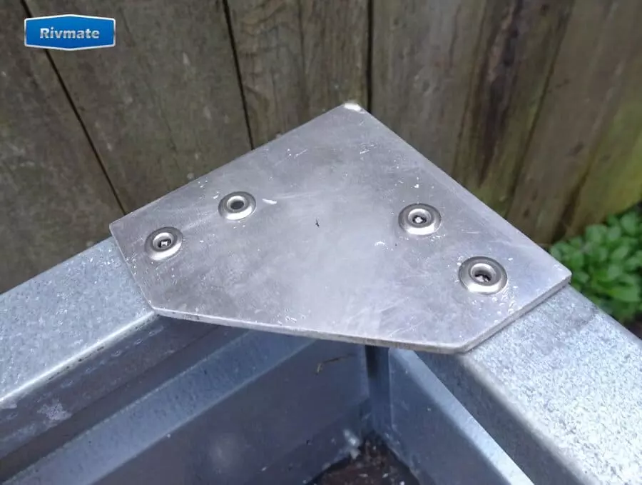
⑥ Clean Finish & Low Maintenance
- The surface is smooth and does not expose any threads. This reduces the risk of scratches and impacts, making it suitable for the exteriors of household appliances, electronic enclosures, and visible components of the passenger cabin.
- The surface treatment and color can be selected (aluminum rivets, coloring caps, closed type, etc.), with high consistency.
- No torque re-inspection is required, and the maintenance frequency is low; it is suitable for products with low accessibility after batch delivery.
Real-World Fits
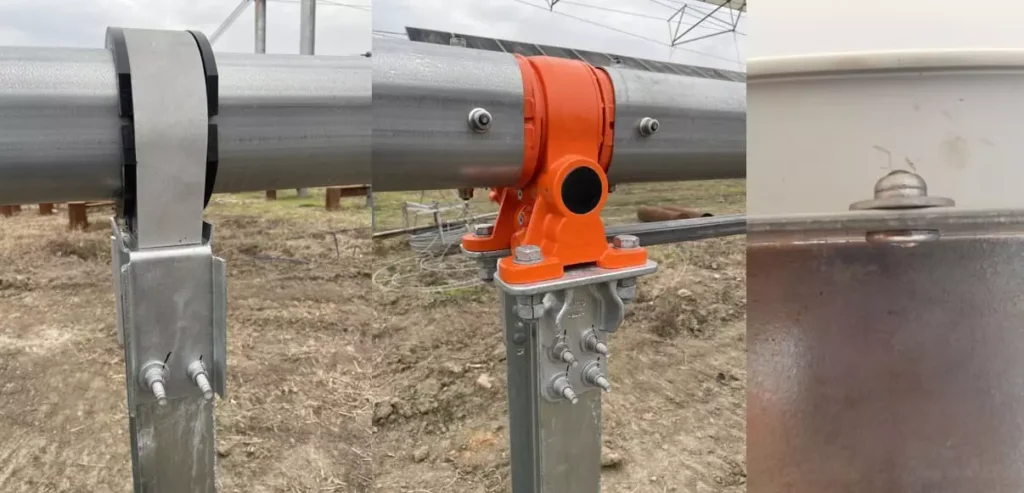
HVAC/Air Duct System: One-sided operation + Fast pace + Low noise, friendly for construction and maintenance.
Automobile Body and Thermal End Components: Resistance to vibration and weight reduction, suitable for thin plates and multi-layer laminates.
Aviation/Railway Interior Decoration and Cabin Components: Lightweighting and Appearance Consistency.
Electronic and household appliance shells: Thin plates, plastic-gold composite materials, with high requirements for the visible surfaces.
Building Metal Curtain Wall / Profiles: Closed profiles, inaccessible areas on the backside.
Data Snapshot
Assembly cycle: Blind riveting 2 – 4 seconds per point vs Screw fastening 8 – 20 seconds per point.
Weight: Typical reduction of 70 – 90% (aluminum blind rivets vs carbon steel bolt system).
Manual: 6 – 16 seconds per point Savings, $4 – $11 per piece (100 points) Direct labor is visible.
Quality inspection and maintenance: For blind riveting, there is no need for torque recheck. For bolts, force and angle control as well as regular inspections are required.
Limitations of Blind Rivets
Although blind rivets have significant advantages in terms of single-sided installation, assembly efficiency, weight reduction, and vibration resistance, they are not a universal solution in all applications. Understanding their limitations can help make more reasonable decisions during the design and selection stages.
a. Permanent connection, difficult to disassemble
After blind rivets are installed, they achieve a permanent locking effect. If removal is required, usually the surrounding material needs to be drilled out or damaged. This implies that they are not suitable for scenarios where frequent disassembly, regular maintenance, or replacement of components are necessary. In contrast, bolt connections offer greater maintainability.
Blind rivets are more suitable for thin sheet metals and medium-strength connections. In extremely heavy and high-stress conditions, such as bridge connections, mining machinery, and main load-bearing parts of wind power, bolts or welding are more reliable. Although there are already high-strength structural blind rivets, in general, bolts still have an advantage in static loads and high shear loads scenarios.
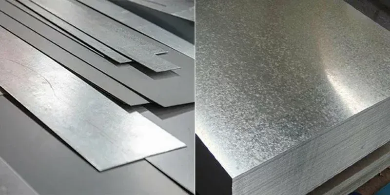
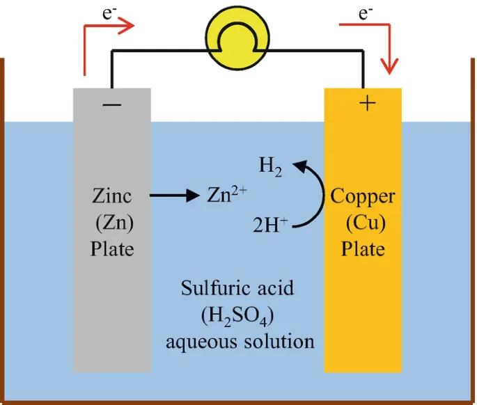
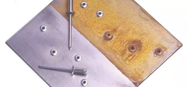
c. Materials and Corrosion Risk
Common materials for blind rivets include aluminum, stainless steel, carbon steel, and coated steel. If the material selection is incorrect, electrochemical corrosion (such as aluminum rivets with carbon steel) may occur. The solution is to choose a material with an electrochemical potential close to that of the base material, or to use coated, anti-corrosion coatings and sealed blind rivets. In marine, chemical, or outdoor environments where exposure is long-term, designers must pay special attention to this issue.
Comparison Table of Blind Rivets and Bolts
During the design phase, engineers usually need to make trade-offs among assembly efficiency, maintenance requirements, load-bearing capacity and cost. The following table visually presents the key differences between blind rivets and bolts:
| Feature | Blind Rivets | Threaded Bolts |
|---|---|---|
| Installation | Single-sided (front access only) | Double-sided (bolt + nut) |
| Installation Speed | Fast (2–4s per point) | Slower (8–20s per point) |
| Removability | No (permanent joint) | Yes (reusable) |
| Vibration Resistance | High (permanent lock) | Lower, may loosen |
| Weight | Light (up to 70–90% reduction) | Heavier |
| Cost Efficiency | Lower (fewer parts, faster assembly, simpler inventory) | Higher (more parts, torque control, frequent checks) |
| Typical Applications | Aerospace, automotive, HVAC, electronics, construction | Heavy machinery, bridges, large assemblies, serviceable structures |
- Blind rivets are more suitable for industries involving mass production, lightweight structures, and limited installation space.
- Screws, on the other hand, are indispensable in scenarios with extremely high load-bearing capacity, the need for repeated disassembly, and long-term maintenance.
Blind rivets represent an efficient and lightweight solution, while bolts represent a solution with high strength and maintainability.
Rivmate Expertise & Solutions
As a professional fastener supplier, Rivmate offers a full range of blind rivet solutions to meet the assembly requirements of various industries. Its products not only cover multiple materials, but also demonstrate a deep understanding of industry scenarios in terms of design and application.
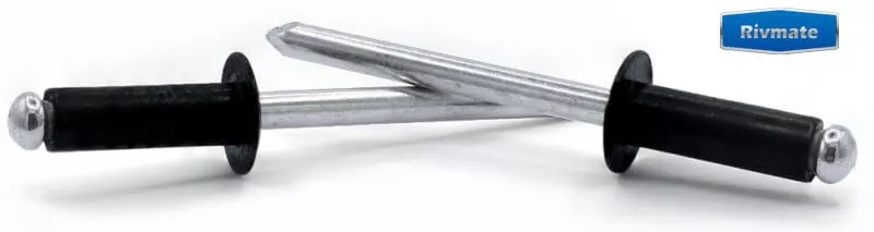
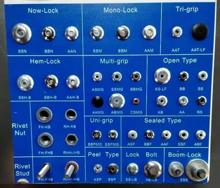
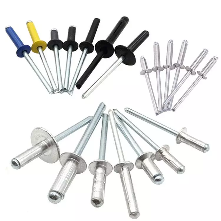
Multiple material options available
The Rivmate blind rivets cover materials such as aluminium, stainless steel, Monel alloy, and copper.
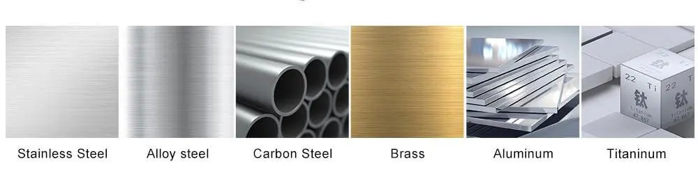
- Aluminum: Lightweight, suitable for automotive and electronic enclosures.
- Stainless Steel: Corrosion-resistant, suitable for construction and outdoor applications.
- Monel Alloy: Resistant to salt fog and chemical media, commonly used in marine and chemical environments.
- Copper: Conductive, suitable for electronics and electrical industries.
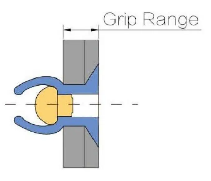
Rivmate’s product design covers a wide range of grip range from thin plates to thick plates. This enables customers to reduce the variety of parts during the design stage and decrease the number of inventory SKUs.
For OEM manufacturers and distributors, it helps to reduce inventory holding costs and enhance supply chain efficiency.
Industry Optimization Series
The Rivmate blind rivets have been developed into customized series for the automotive, construction and electronics industries.
- Automobile: Body panels, exhaust system, lightweight components.
- Construction: Curtain walls, steel structure joints, HVAC system.
- Electronic industry: Connection of metal and plastic shells to ensure both aesthetics and durability.
Technical Support and Value-added Services
Rivmate not only offers products, but also provides full-process technical support:
- Model Selection Support: Assist customers in choosing the optimal model based on materials, loads, and environments.
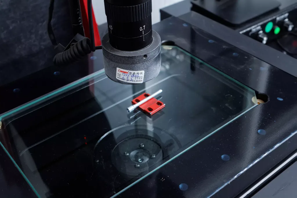
- Strength Verification: Through data testing and experiments, ensure the reliability of the connection.
- Inventory Optimization: Help customers reduce the number of SKUs and achieve lower inventory and higher turnover.
FAQ
Q1: Can blind rivets replace all bolts?
No. Blind rivets are suitable for scenarios of single-sided installation, lightweight and batch production. However, in super heavy-duty structures, high-load areas or situations requiring frequent disassembly, bolts still cannot be replaced. Engineers should make reasonable selections based on load, material thickness, and maintenance requirements.
Q2: Can the blind rivets be removed after installation?
Blind rivets are of permanent connection. If disassembly is required, usually drilling or cutting is needed, which may damage the base material. Therefore, it is not recommended to use blind rivets in areas where repeated assembly or maintenance is necessary. In such scenarios, bolts or screws are more suitable.
Q3: How should one choose blind rivets in high-intensity or high-temperature environments?
It is advisable to choose structural blind rivets or high-performance materials (such as stainless steel, Monel alloy).
- High-strength Requirements: It is recommended to use structural blind rivets, as their clamping force and shear resistance are superior to those of conventional products.
- High Temperature Environment: Avoid using aluminum materials and instead choose stainless steel or nickel-based alloy blind rivets.
At the same time, reference should be made to international standards such as ISO 15977 to ensure that the selection meets the load and safety requirements.
Q4: Can Rivmate offer alternative solutions to reduce the assembly costs?
Sure. Rivmate not only offers blind rivet products, but also provides services such as specification optimization, strength verification and inventory management.
- By reducing the number of SKUs, the inventory holding cost can be lowered.
- By implementing rapid installation, the labor cost can be reduced.
- By matching the appropriate materials, the rework and maintenance costs can be decreased.
Choose Smarter Fastening, Choose Rivmate

Blind rivets have significant advantages over bolts in most medium and light applications. They perform better in terms of installation efficiency, structural weight reduction, cost-effectiveness, and vibration resistance. Particularly in industries such as automobiles, aviation, electronic enclosures, and construction, blind rivets can help manufacturers achieve faster production line cycle times, lower total costs, and higher reliability.
If you are currently struggling with the selection of bolts and blind rivets, or if you wish to further reduce the assembly cost, please feel free to contact Rivmate.
- Obtain the professional “Blind Rivet vs. Bolt Selection Guide”;
- Consult our engineering team to obtain the “optimal solution tailored to your product and process”.
📞 Act Immediately: Partner with Rivmate and enhance your competitiveness with a more professional fastening solution.
Reference

Are Rivets Waterproof?
Are Blind Rivets Waterpro

The Comprehensive Guide to Open End Blind Rivets
the comprehensive guide t

How to Rivet Metal to Wood?
How to Rivet Metal to Woo

What Is Riveting in Metal Work?
What Is Riveting in Metal