Whatsapp: +86 18962304392

Email: manufacture@world-rivet.com

[bellows config_id="main" menu="39"]
Contact Us

manufacture@world-rivet.com

+86 189 6230 4392

Room 9016 of 2# Building, No. 436 Changjiang Road, Suzhou City, Jiangsu Province, China 215011.

Certificate

Blind Riveting Design Guide

Table of Contents

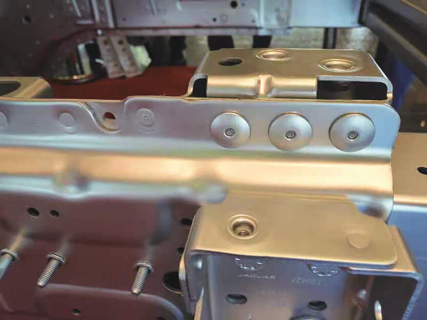
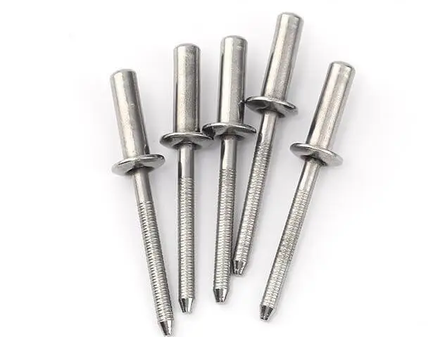
Blind riveting is a simple operation that does not require back support. It is widely used in various fields such as sheet metal connections and shell structures. In actual engineering, blind rivets directly affect the strength and assembly consistency of the entire structure. The key parameters for riveting connections during the design stage are of great significance. These include aspects such as the accuracy of hole positions, the selection of rivet types, the matching of rivet head shapes, and the layout method (such as spacing and arrangement direction). If these are overlooked, it is highly likely to result in the following problems:

  • Structural failure or loose connections
  • Accelerated expansion of fatigue cracks
  • Interference or mismatch during installation
  • Affecting the service life and safety of the product


Therefore, developing a professional and systematic Riveting Design Guide is of vital importance for ensuring structural stability, enhancing assembly efficiency, and reducing the risks of later maintenance. This article will delve into the key technologies in blind riveting design from aspects such as design points, material selection, and mechanical analysis. It aims to assist engineers in avoiding potential problems at an early stage and creating a more reliable connection system.

Fundamentals of Blind Riveting Design Based on Mechanical Principles

Types of Blind Rivets

Blind riveting is a non-detachable connection method widely used in aviation, automobiles, electronics and sheet metal structures. Its structural design must be based on precise mechanical principles to ensure long-term reliability and safety. The following explains the key design points starting from the force mechanism, which is applicable to structural engineers, product developers and quality engineers.

Analysis of the Force Mechanism

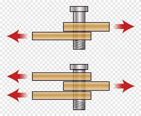
  1. Shear Load Concentration
    In most applications, rivets mainly bear shear loads. Blind rivets, due to their closed structure at one end, usually have an incompletely symmetrical shear surface. This may cause shear stress to concentrate in the area close to the point where the rivet rod breaks. If the hole position is improperly designed, it can easily lead to local yielding or the accumulation of micro-cracks, thereby weakening the connection strength.
  2. Tensile Load Path
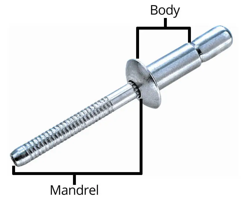
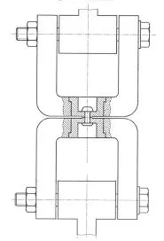
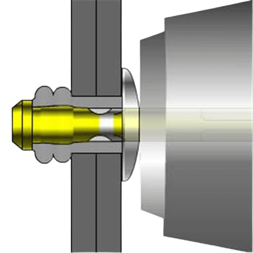
    When subjected to tension (such as when a sheet is pulled apart along the vertical direction), the blind rivet converts the tension into the clamping force between the two plates through its “pulling pin tail ball head”. However, the tension path is long, which makes it prone to causing slight deformation along the axial direction of the rivet. If the fit between the rivet rod and the hole is too loose, it may result in micro wear.
  3. Impact of Fatigue Cycles
    Under repeated loads (such as vibration or periodic forces), the riveted area becomes a region with high stress concentration, especially when there is a gap between the rivet rod and the hole wall. Fatigue cracks often originate from the edge of the hole or the clamping surface. Therefore, a reasonable design of pre-tightening force and control of hole spacing are the key to improving fatigue life.

Key Points of Structural Design

What are monobolt rivets
  1. Rivet Pattern
    The rivets should be evenly distributed along the load path to avoid interruption or premature change of the force flow. Usually, a “trapezoidal” or “rhombic” arrangement is adopted to achieve stress diffusion. Although continuous linear arrangement is convenient for assembly, it may result in concentrated force. The arrangement should be optimized according to the actual load direction.
  2. Pitch and Edge Distance
    • Pitch: It should be greater than 2.5D (D is the diameter of the rivet), to prevent the overlapping of the cutting surfaces and the resulting material tearing.
    • Edge Distance: It is recommended to be ≥ 2D, to avoid edge cracks or edge deformation, especially in low-strength materials such as aluminum and magnesium, where caution should be exercised.
  3. Load Path Architecture
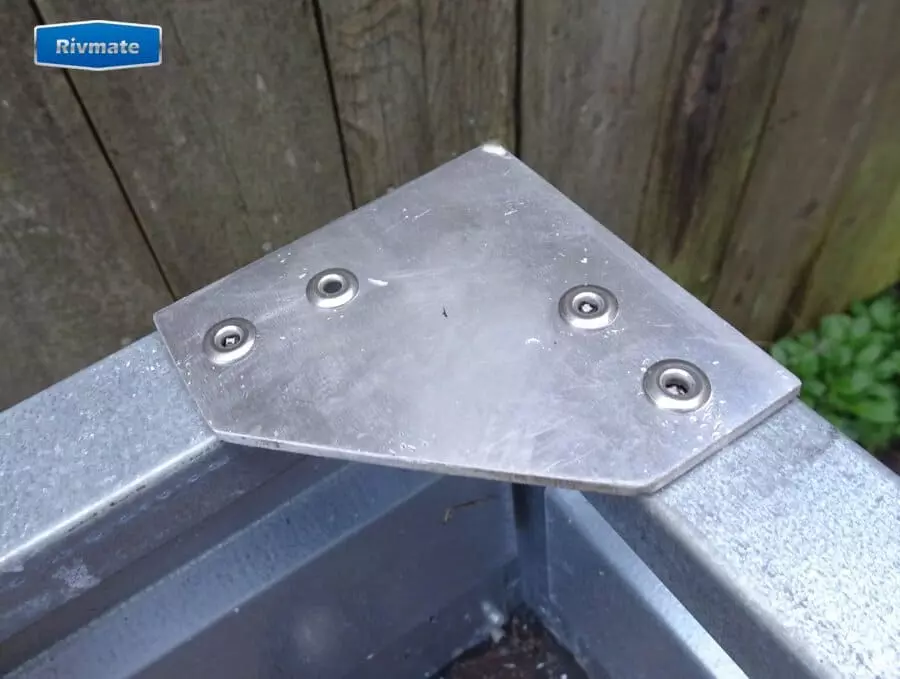
    It is necessary to ensure that the force flow of all connection nodes is continuous, and avoid “floating” or “bridging” designs. For example, using triangular reinforcement plates combined with blind rivets at structural corners to distribute the load can effectively prevent stress concentration.
  4. Distribution of Force Direction
    Bolt connections are best used for connections in the direction of shear, avoiding applications where axial tension is the main force. If tension is unavoidable in the design, structural reinforcements (such as washers, conical seats) should be used to enhance the tensile resistance.

Key Design Parameters for Reliable Blind Riveting

When conducting the blind riveting design, the structural strength, durability and manufacturing feasibility all depend on a series of detailed parameter designs. The following explains five key elements, providing professional suggestions based on actual working conditions. Ensure stable connection quality, reasonable stress distribution, and reduce the risks of corrosion and fatigue.

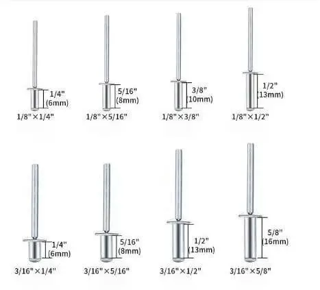
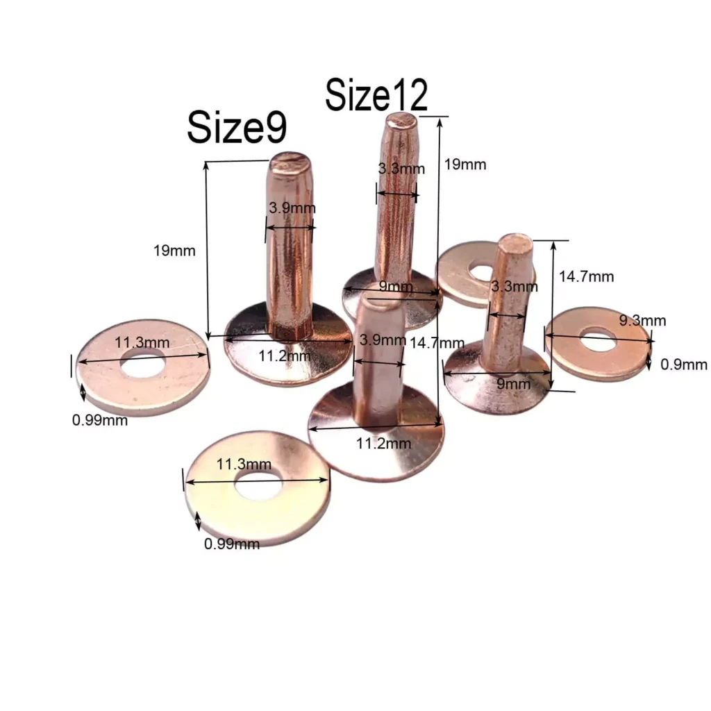
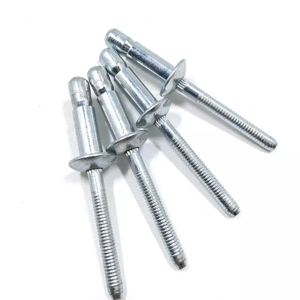
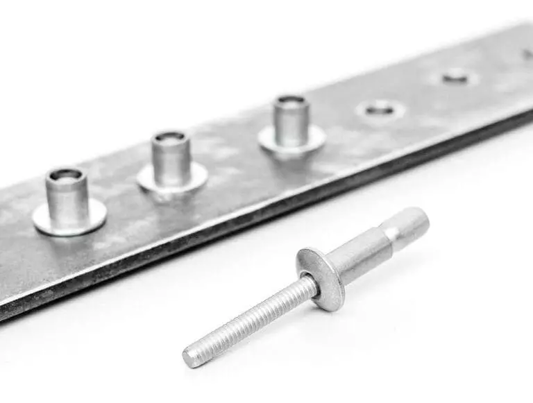
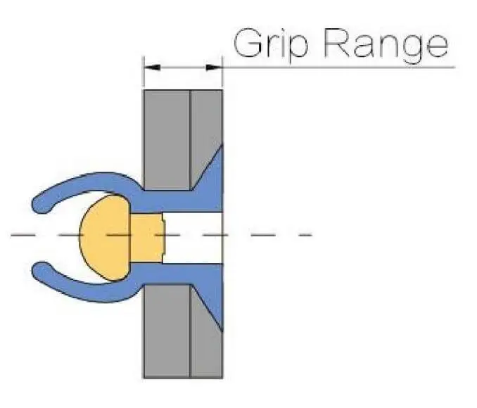
a. Bolt Type, Rod Diameter and Grip Range

How to Choose the Appropriate Rivet Grip Range
The “holding range” refers to the total thickness of the material that the rivet can effectively grip (the combined thickness of the two plates). It is necessary to ensure that the total plate thickness falls within the middle value of the selected rivet’s Grip Range plus or minus 10%. If it is too small, it will result in unstable gripping; if it is too large, it will create a blind end residual gap, causing the structure to loosen.

the grip range of blind rivet

The influence of rod diameter on shear/tear strength
The shear strength of the rivet is in a square relationship with the diameter of the rod, while the drawing strength is affected by the shape of the head and the deformation form at the tail. For example:

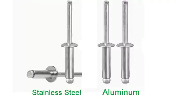
  • 3/16″ (4.8 mm) aluminum rivets have a shear strength of approximately 800 – 1,000 N
  • 3/16″ stainless steel rivets can achieve a shear strength of over 2,000 N (The specific values should be referred to the manufacturer’s data sheet.)

In the design process, an appropriate rod diameter and material should be selected after the load direction is clearly defined.

b. Hole Diameter and Fit Tolerance

The Influence of Hole Size on Tensile Force and Clamping Effect

An excessively large hole size will result in “empty motion” under axial force, leading to micro-movement wear; while a too small bore diameter is prone to causing installation difficulties or compression damage. The correct hole size design should be slightly larger than the rod diameter, allowing for a smooth insertion while ensuring good contact.

Suggested Aperture Margin

  • The recommended range is bolt rod diameter +0.003″ to +0.005″ (0.08—0.13 mm)
  • For stainless steel materials or precision structures, it can be controlled to +0.002″

It is essential to prevent the formation of burrs or elliptical deformations on the hole walls, as these can significantly reduce the fatigue life.

c. Layout Parameters: Edge Distance, Center Distance and Line Spacing

Recommendation Ratio Rule

  • Edge Distance (Margin) ≥ 2D: Prevents edge materials from tearing, especially in soft metals such as aluminum.
  • Pitch (Center Distance) ≥ 3D: Avoids overlapping of the cutting surface or stress concentration.
  • Row Spacing (Row Distance) ≥ 2.5D: Ensures structural integrity when multiple rows of rivets are used.

Asymmetric Force Flow Design Suggestions

For structures with non-uniform load directions (such as trapezoidal connection areas), offset arrangement or “interlaced layout” should be used to distribute the stress. For example, by staggering the middle row by half a pitch to form a triangular grid, the fatigue life can be increased by more than 30%.

Types of Rivet Heads
Different Types of Rivet Heads
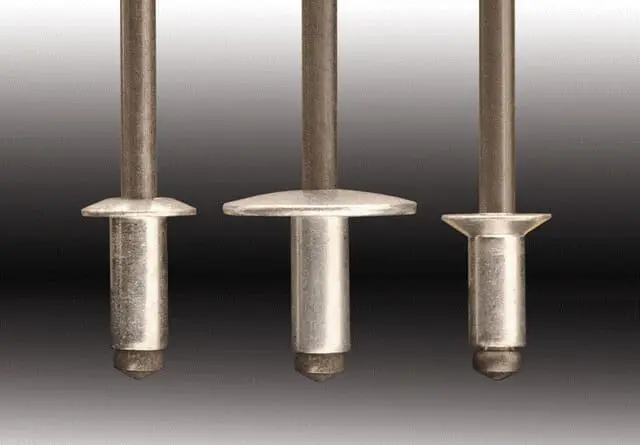
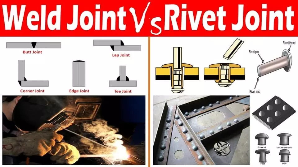
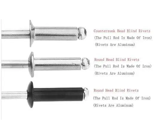
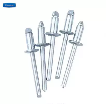
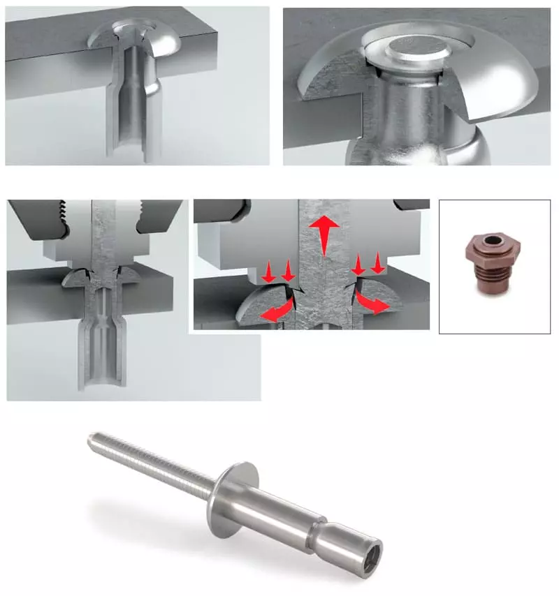
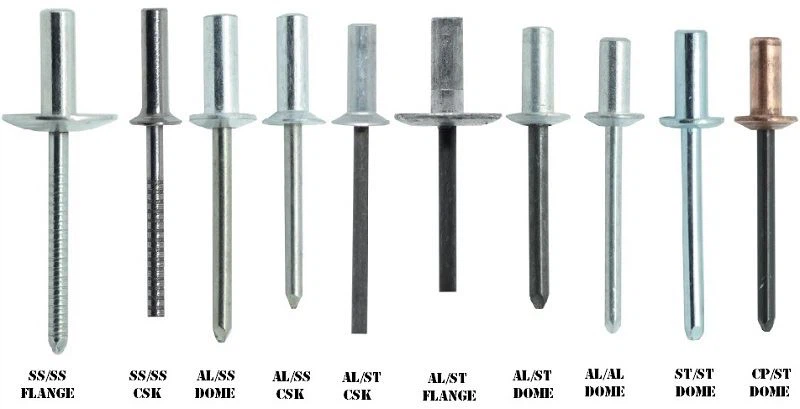
  • Dome Head (Round Head): Universal type, with moderate contact area, suitable for most metal plate connections
  • Countersunk Head (Sunk Head): Used for structures requiring a flat surface alignment, suitable for areas with low stress or for appearance requirements, but has a small clamping area and should avoid high load usage
  • Large Flange Head (Large Flange): Suitable for soft materials such as plastics and composite boards, with good distribution of load, preventing surface indentation and cracking

The choice of hairstyle should be based on a balance between the hardness of the base material and functional requirements. It is not recommended to make a decision solely based on cost.

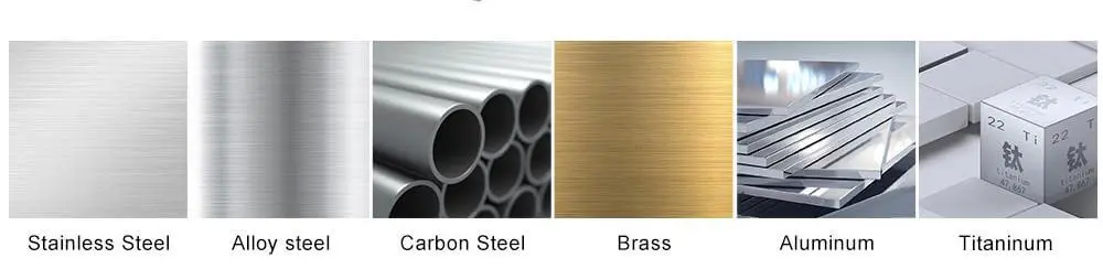
e. Material Matching and Corrosion Prevention Design

Electrochemical corrosion risk

When the material of the rivets has a significant potential difference from the base material (for example, aluminum plate paired with stainless steel rivets), it is prone to form galvanic corrosion in humid or salt-spray environments. The design should consider the following matching strategies:

  • Priority given to the same material (such as aluminum versus aluminum, stainless steel versus stainless steel)
  • If avoidance is not possible, insulating washers or anti-corrosion coatings should be used instead.

Waterproof Sealing Design

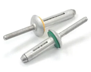
For outdoor or enclosed structure applications, it is recommended to choose those that have:

  • Rubber sealed tail design (sealed rivet)
  • Or it can be used in combination with a sealing washer (neoprene washer)

This type of design can effectively prevent moisture from penetrating into the intermediate layer, thereby extending the service life.

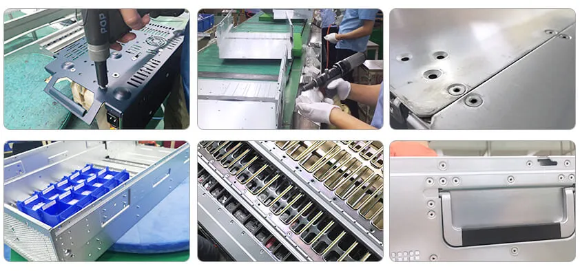
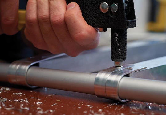
Practical Workflow for Implementing Blind Riveting in Engineering Design

During the product structure design phase, the introduction of the “blind riveting solution” requires a systematic consideration of material stacking, mechanical structure, processing accuracy, and batch assembly efficiency. The entire process is recommended to be divided into two stages: the “design decision stage” and the “manufacturing implementation stage”. At each stage, a verification mechanism should be established at key nodes to ensure that each rivet from the drawing to the product is controllable and consistent.

Design Decision Phase

The primary task is to accurately assess the material thickness at all connection points, including nominal thickness, tolerance, surface treatment, and functional coating layers. For instance, electrophoretic coatings and sealants can add additional thickness. If not accounted for, this will result in insufficient gripping or abnormal tail deformation. When selecting rivets, the Grip Range should be strictly used for selection to ensure that the total stack thickness falls within the middle-upper part of the clamping range, and avoid using total length as a substitute for Grip specifications. Additionally, when positioning and arranging the rivets in CAD, the layout should be optimized based on the structural force direction (such as triangular grid layout can improve fatigue life), and the basic design specifications of margin ≥ 2D and center distance ≥ 3D should be maintained to avoid sheet tearing or deformation due to too dense arrangement or being close to the edge.
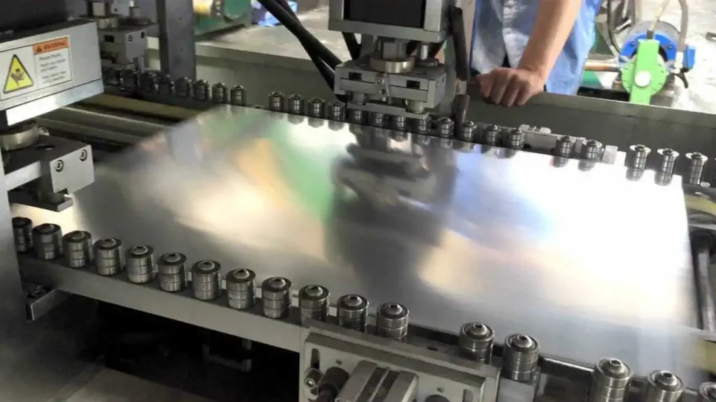
Manufacturing Phase

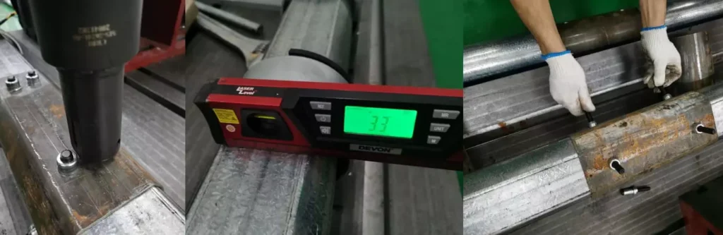
The key points lie in the quality control of hole processing and the setting of assembly process parameters. The hole diameter must meet the recommended fit tolerance (generally the rod diameter +0.003″ to +0.005″), and must maintain roundness and perpendicularity to prevent uneven loading or micro-motion after the pin is inserted. The production line should use automated or semi-automated riveting equipment, preset parameters for tension, stroke and time window, and lock and trace them through the industrial control system or MES platform. Key positions should implement the first-piece full inspection and process sampling inspection mechanism to ensure that the clamping force, tail deformation quality and surface indentation are within the control range.

Common Mistakes in Blind Riveting Design and How to Avoid Them

① Ignoring the tolerance of plate thickness leads to insufficient clamping force

Do Zinc Plated Rivets Rust

Common Misconceptions:
During the design process, the selection of rivets was solely based on the nominal thickness of the plate, ignoring the actual thickness tolerance of the material and the coating thickness. This resulted in a smaller or excessive grip range of the rivets, affecting the clamping force and deformation control.

Consequences:

  • Residual gap between plates → Causes loosening or structural “shaking”
  • Insufficient tail deformation → Clamping failure or incomplete riveting

Avoidance Suggestions:

  • When calculating the total thickness, the following factors should be taken into account: ±sheet thickness tolerance + coating thickness + film thickness
  • Prefer to choose the specifications whose gripping range is located in the middle of the total thickness by ±15%
  • For mass production, a thickness grading table should be used to assist in selection

②. Incorrectly Taking the Total Length of the Rivets as the Design Basis

Common Misconceptions:
Some designers mistakenly used the total length of the rivets to match the plate thickness, ignoring the structural differences between it and the grip range.

Consequence:

  • The rear end did not deform correctly after installation.
  • The gun cannot complete the disconnection action after being installed.

Avoidance Suggestions:

  • Design strictly according to “Grip Range” rather than “Total Length”
  • All drawings or BOM annotations should indicate the “Grip” parameter, not the total length

③. Excessive spacing between nails or insufficient margins

Common Misconceptions
Due to the need for stronger connections or space constraints, the spacing of the rivets was designed too small, even violating the minimum Pitch and edge distance rules. Consequences:

  • Board cracks along the edge of the hole
  • Local warping or deformation, reducing fatigue life

Avoidance Suggestions:

  • Follow the experience rule: Pitch ≥ 3D, Edge Distance ≥ 2D
  • When the material is relatively soft (such as aluminum, plastic), it is recommended to increase the margin to ≥ 2.5D
  • Avoid using rivets close to weakened areas such as folded edges, slots, or punching holes

④. Incompatibility of materials causes galvanic corrosion

Common Misconceptions:
To achieve higher strength or lower costs, unassessed combinations of dissimilar metals such as stainless steel nails with aluminum plates or copper nails with galvanized parts were adopted.

Consequences:

  • Forming an electrochemical corrosion circuit in a humid environment
  • The corrosion spreads from around the rivet hole and eventually leads to failure

Avoidance Suggestions:

  • Use the same or similar metal materials (such as aluminum paired with aluminum, stainless steel paired with stainless steel)
  • If unavoidable, add anti-corrosion measures (epoxy coating, sealing the tail end, nitrile rubber gasket)
  • For important structures, conduct accelerated corrosion tests using ASTM G44/G85

⑤. Ignore the effects of thermal expansion and contraction or dynamic loading conditions

Common Misconceptions
Structures that are exposed to alternating temperatures, high-frequency vibrations or near heat sources do not have stress release designs for the rivets, and are still designed according to the normal temperature static load scheme.

Consequences:

  • The material expands thermally, resulting in internal stress.
  • The rivets develop fatigue cracks or undergo creep loosening.

Avoidance Suggestions:

  • In areas with significant thermal deformation, use a floating hole design or elastic gaskets
  • In high-frequency vibration environments, adopt a tail-locking structure (such as Huck Bolt) or enhance the clamping force

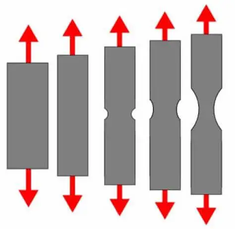
Validation and Quality Control in Blind Riveting Design

In terms of design verification, it is recommended to prioritize the introduction of finite element analysis (FEA) to conduct stress simulations at key riveting points, identifying stress concentration areas, fatigue hotspots, and potential failure risks. This is especially necessary in cases of variable loads, thermal-cold cycling, or eccentric loading. For the structural prototype stage, standard tensile/shear tests should be conducted to verify whether the rivets’ load-bearing capacity meets the design requirements, and at the same time, perform fatigue cycle tests (such as according to the ASTM E466 standard) to assess the durability of the structure over a long period of use. If there are multi-material or mixed connection structures, comprehensive tests such as vibration tables and climate chambers can also be introduced to simulate multiple factors of environmental conditions.

In terms of the quality control system, it is recommended to establish standardized SOP (Standard Operating Procedures) covering all stages from incoming material inspection, hole processing, rivet assembly to final inspection; in conjunction with special installation clamps and fixtures, ensure the consistency of workers’ clamping force and reduce human errors. At the same time, a tolerance caliper inspection standard needs to be formulated, regularly measuring key dimensions such as hole diameter, edge distance, and tail deformation, and introducing a regular quality inspection mechanism (e.g., every 500 pieces / every shift), recording the measurement data in the quality traceability system to achieve full-process closed-loop control.

Reference

Share:

More Posts

Get Rivets Quotes Now

Wholesale Blind Rivets from Rivet Manufacturer

Common Rivet Installation Mistakes - How to Avoid When Using Rivet

Table of Contents

In industrial manufacturing and daily maintenance, rivet connections are efficient, reliable and do not require tapping. However, the seemingly simple riveting process often harbors risks. Errors in rivet installation are easily overlooked by operators. In reality, they may become the root cause of structural loosening, water seepage, rusting and even failure. To understand and avoid these issues, this article will systematically summarize the common mistakes to avoid when using rivets in practical applications. Combined with engineering cases, it will provide a series of professional and actionable prevention and correction suggestions to help technicians, purchasing engineers and production managers improve riveting quality and extend product service life.

The Basic Principles and Installation Process of Rivet Connections

Applications of Interlcok Blind Rivets - Cabinets and Enclosures

Bolt connection is a type of connection that achieves permanent mechanical fixation through plastic deformation. It is widely used in the structural assembly between metals, plastics, and composite materials. Depending on the structural requirements and the installation tools, the common types of bolts include the following:

  • Solid Rivets: Have a long history and are suitable for high-strength structures, such as in aviation and bridges. Installation requires double-sided operation.
  • Blind Rivets: Also known as blind rivets, they are suitable for single-sided contact conditions and are commonly used in sheet metal parts, appliance shells, etc.
  • Structural Rivets: Based on the principles of blind rivets, they have enhanced shear strength and vibration resistance, and are often used in high-load scenarios such as vehicles and construction machinery.

  1. Drilling: Select the appropriate hole diameter based on the diameter of the rivet to ensure the hole wall is smooth and free of burrs.
  2. Inserting the Rivet: Insert the rivet into the hole of the workpiece, ensuring a tight fit.
  3. Breaking/Securing: Use a special tool to apply tension to the mandrel or lock the nail rod, causing the tail end to expand and form, completing the fixation.
  4. Installation Inspection: Confirm that the head of the rivet is tightly attached to the workpiece, and the tail end is fully deformed without cracks, ensuring the integrity of the structure.

The quality of rivet installation has a direct impact on the structural performance, which is mainly manifested as:

  • Shear strength: If the rivets are not tightly attached or the hole diameters are too large, it can lead to uneven force distribution, thereby reducing the overall connection strength.
  • Waterproofing: If the rivets are not compacted or the installation angles are incorrect, it can result in gaps, causing leakage problems.
  • Fatigue life: An improper breaking process may introduce residual stress, affecting long-term stability and increasing the risk of fatigue failure.

Top 10 Common Errors in Rivet Installation and Analysis of Their Causes

Common mistakes and ways to avoid them when using rivets on solar panels

Although rivets are small, they directly affect the overall stability and service life of the connection structure. Here are the most common mistakes to avoid when using rivets in actual engineering projects. Each one is worthy of attention and is accompanied by practical corrective suggestions.

①. Misalignment of aperture (too large/ too small)

When the aperture is too large: The rivets will shake within the holes, causing the connection to become loose, the shear force to decrease, and even falling off in a vibrating environment; When the aperture is too small: The rivets are difficult to insert, which may cause scratches or deformation on the surface of the rivets, further affecting the riveting strength and sealing effect. Solutions Proposed:

  • Follow the reasonable ratio between the diameter of the rivet and the diameter of the hole. Generally, it is recommended that the hole diameter = rivet diameter + 0.1 to 0.2 mm;
  • Refer to the rivet hole size chart provided by the manufacturer
  • Refer to the drill bit size comparison table provided by the manufacturer and use dedicated drill bits to ensure accuracy.

②. Incorrect determination of clamping thickness

The grip range of the rivet is a key parameter that determines its performance. If the clamping range of the rivets is less than the total thickness of the sheet material, the rivet feet cannot fully expand, resulting in loosening or failure of the riveted connection.

On the contrary, if the clamping range is too large and the nail head shrinks excessively, it is also prone to deformation and bulging, which will affect the structural strength and appearance.

Therefore, accurately determining the total thickness of the workpiece and selecting the appropriate clamping range for the rivets is the fundamental requirement for avoiding the mistakes when using rivets.

③. Incorrect selection of Rivet Length

The length of the rivet determines whether it can effectively cover the connecting material. Rivets that are too short cannot grip the sheet metal tightly and are prone to the “empty pull” phenomenon, resulting in an insecure connection. On the other hand, rivets that are too long are likely to bulge or deform at the nail head during the riveting process, thereby compromising the structural integrity.

How Do I Choose The Right Size Pop Rivet? - Select the Length of the Pop Rivets

The general principle for reasonably selecting the length of the rivets is: Grip Range = Total Thickness of the Plate ± Tolerance. This judgment criterion should be clearly defined before the design and construction.

④. Installation with Angle Deviation

When the rivets are not perpendicular to the connection plate surface, during the riveting process, the rivet tail will be skewed and spread out. This may lead to problems such as cracks and uneven internal stress in the structure.

When the rivets are not inserted vertically into the holes, resulting in an inclined installation, the axis of the rivets forms an angle with the plate surface, leading to uneven stress distribution. The expansion of the rivet feet is asymmetric, which is very likely to cause material cracking, surface warping or sealing failure. Especially in high-strength connections or structural riveting, such problems will seriously reduce the shear and tensile performance.

Avoid such mistakes when using rivets, and instead use positioning fixtures or alignment devices to assist in the installation, ensuring verticality.

⑤. Failure to remove burrs at the edge of the hole or surface contamination

Impurities such as burrs, oil stains, and iron filings at the hole edges can affect the bonding density of the rivets, leading to sealing failure and even initiating corrosion.

  • Perform edge deburring treatment around the holes before riveting;
  • Clean the riveting area to ensure a clean and flat surface.

⑥. Incorrect Tool Settings

If the pulling force setting of an air or electric pull-pin gun is not reasonable, it will directly affect the locking effect of the rivets.

Use Air Rivet Nut Tool

If the clamping force is too small, the rivet will not be fully locked, resulting in a situation where it is partially pulled or loose. If the clamping force is too large, it may cause the pull pin to break, the rivet to be misaligned, or the sheet material to be damaged.

Different materials and specifications of rivets need to be matched with corresponding set values. The installation personnel should calibrate the equipment regularly.

⑦. Ignore Sealing Measures

When using nails or sealing gaskets in outdoor or humid environments, if they are not of the enclosed type, problems such as water seepage, rusting, and leakage are likely to occur. It is recommended:

  • In sealed application scenarios, choose Closed-End Rivets (closed-type rivets);
  • Use in conjunction with rubber gaskets or sealants to enhance the protection level.

⑧. Using low-quality or mismatched rivets

The material of the rivets should match that of the connecting components; otherwise, electrochemical corrosion is likely to occur. Especially when carbon steel rivets are used in aluminum plates, problems such as corrosion damage, darkening of color, and reduced strength often arise. Moreover, inferior rivets have poor processing accuracy and easily break the core rod, frequently causing structural expansion and deformation, or even fracture during use. To avoid such mistakes when using rivets, it is necessary to select regular brand products with quality certification. And the material should be chosen according to the working environment (such as stainless steel, aluminum, copper, etc.).

⑨. Rivets are not properly centered and aligned

If the installation position of the rivet is not accurately aligned with the hole: it will affect the uniformity of the rivet tail expansion, reduce the connection strength and affect the consistency of the appearance.

If the center of the rivet is not accurately aligned with the hole position: during installation, eccentric force will occur, reducing the shear bearing capacity and also affecting the flatness of the appearance.

Especially in decorative panels and precision components, the alignment deviation can lead to significant uneven stress, which may cause crack propagation or failure. This can be achieved through:

  • Use laser drilling or CNC drilling equipment to ensure high-precision alignment;
  • Conduct manual inspection to confirm that the hole positions are concentric.

⑩. Failure to conduct post-operation inspection

Failure to conduct the necessary tail extension inspection after riveting is the most easily overlooked yet high-risk operational error. If the core is not broken, the broken part is unstable, or the nail feet do not fully extend, the connection strength will be greatly reduced, and the connection may fail rapidly during use. It is recommended to conduct a post-riveting inspection after each batch of construction. This includes observing the tail condition, conducting random destructive tests, etc., which are the basic operational norms for controlling the reliability of riveting.

How to Avoid Installation Mistakes When Using Rivets?

To ensure the firmness and durability of the rivet connection, it is crucial to master the correct rivet installation method. Below are the common types of problems and their corresponding preventive measures and recommended tools, which will help you complete the riveting work efficiently and avoid errors.

Type of MistakePrevention MethodRecommended Tools/Assistive Devices
Incorrect Hole SizeFollow rivet specifications strictly to avoid oversized or undersized holesUse depth-limiting drill bits, verify with calipers, refer to rivet size charts
Misaligned Installation AngleEnsure the rivet is installed perpendicular to the work surfaceUse vertical positioning jigs, assist with laser alignment or marking tools
Incorrect Rivet Length SelectionChoose the correct rivet based on total material thickness (Grip Range)Use Grip Range calculators (e.g., Excel tools), consult manufacturer handbooks
Improper Tool SettingsEnsure the pull force is correctly set for the specific rivetCalibrate regularly with a pull tester, use air pressure regulators for pneumatic tools
Material IncompatibilityPrevent galvanic corrosion by using compatible metal combinationsRefer to a galvanic corrosion chart to select metals with minimal potential difference

How to confirm if it is installed correctly after installation?

How to Install Countersunk Rivets

To ensure that each rivet installation meets the quality standards, it is recommended to conduct the following checks and verifications:

Critical Checkpoints:

  • Nail head symmetry: The nail head should be firmly in contact with the surface of the workpiece, without being tilted or deformed.
  • Tail end expansion integrity: The tail end should fully expand, securely clamping the base material, without any detachment or loose connection.
  • No cracks on the plate surface: The plates in the riveted area should have no obvious cracks, bulges, or stress marks.

Recommended Tools:

  • Expansion Inspection Gauge: Quickly determine whether the tail end expansion meets the standard.
  • Bolt Strength Pull Test Instrument: Conduct random inspections on key structures to verify if the tensile force meets the requirements.

Quality Traceability Suggestions:

Establish a standardized installation record sheet, including key information such as tool settings, inspection results, and operator signatures, and document each abnormal situation with pictures and text to form a complete feedback loop mechanism, which facilitates continuous optimization of the installation process.

Examples of Common Error Scenarios

Fully Automatic Installation of Blind Rivets

1. Installation with tilted angle vs. Correct vertical connection

Error manifestation: During the installation of the rivets, the gun head was tilted, resulting in eccentricity of the pull pin, and the expansion of the rivet tail was asymmetrical. This made it prone to instability in clamping and loosening of the rivets.

Correct Method: Ensure that the stud gun is kept perpendicular to the surface of the workpiece. Use positioning fixtures or laser-assisted positioning devices to help stabilize the direction and improve the consistency of the riveting.

2. Excessive hole diameter leads to failure of the rotating function of the core-pulling rivet

Error manifestation: The diameter of the hole exceeds the recommended range for the rivet, preventing the rivet from generating sufficient frictional force with the hole wall. During the installation process, “idling” occurs and the tail end deformation cannot be completed.

Prevention Suggestions:

  • Use the limiting drill bit to control the hole diameter;
  • Refer to the pop rivet hole size chart to strictly match the recommended hole size;
  • For critical areas, you can increase the frequency of inspection with the inspection calipers.

3. Comparison between Half-Expanded and Normal Expanded Tail States

Error manifestation: Some rivets failed to fully expand at the tail end due to insufficient tension setting, premature return of the gun head, or too short rivets (commonly referred to as “half-pulled”). The connection strength significantly decreased.

Identification Method

  • Observe whether the tail shape is symmetrical and plump;
  • Quickly screen suspicious areas using the “expansion inspection gauge”;
  • For key structures, it is recommended to use the “pull-out tester” to verify the installation strength.

FAQs

What if the rivets cannot be pulled out?

The possible reasons are as follows:

  • Incorrect selection of rivet diameter or length leads to excessive load on the core;
  • Incompatible model of pull pin gun results in insufficient power or worn-out grippers, making it impossible to grip the core tightly;
  • There are burrs or impurities inside the hole, causing the tail to fail to expand smoothly;
  • The rivet material is too hard (such as stainless steel). It is recommended to use reinforced pneumatic or electric tools.

Solutions Proposed: First, confirm whether the rivet specifications match the firearm. Clean any foreign objects inside the holes. Then, check the wear condition of the clamping爪 of the pull pin gun or replace it with a tool that has greater pulling force.

The core puller broke but didn't grip tightly? Can it be remedied?

This situation is usually referred to as “cracking of the core but no formation”. The following are the handling methods:

  • Minor deformation: You can try using a special core extraction tool to remove the broken core, and then re-bolt it;
  • The bolt is stuck: It is recommended to remove the entire bolt (using a special bolt removal drill), and then reinstall it;
  • If using stainless steel bolts, it is recommended to avoid forcibly extracting to prevent damage to the base material.

Prevention Tips: Check the condition of the gun clamping mechanism to ensure stable force output; if the pull pin is rusty or has burrs, it will also increase the risk of breakage.

How to determine if the rivet clamping force meets the standard?

To determine whether the clamping force meets the standards, one can start from the following aspects:

  • Tail appearance inspection: The qualified rivet tail should be symmetrically and fully expanded, without any skew or creasing;
  • Manual inspection: Gently twist the riveted part, and there should be no looseness;
  • Torque test or pull test: For critical structures, it is recommended to use professional testing instruments to confirm the connection strength;
  • Destructive sampling inspection: Sample the already riveted part for dissection, and observe whether the tail end deformation completely clamps the sheet metal.

Why do aluminium rivets start to rust after only a few months?

Aluminum itself does not rust. However, if corrosion occurs, the reasons usually include:

  • The environment contains salts, acids, bases or industrial pollutants, which accelerate the corrosion of aluminum materials;
  • It is combined with carbon steel core wires, causing electrochemical corrosion (contact between different metals);
  • The surface is not anodized, making the aluminum material more prone to corrosion when exposed to harsh environments;
  • Water accumulates in the structure, accelerating oxidation.

Suggested Usage:

  • For outdoor or humid environments, it is recommended to use all-aluminum or stainless steel rivets;
  • Avoid mixed structures of aluminum and steel;
  • Or choose industrial-grade rivet products with anti-corrosion coating.

Conclusion: How to Avoid Installation Errors When Using Rivet

Although the installation process of rivets may seem simple on the surface, it actually directly affects the strength of the structural connection, the anti-corrosion ability, the sealing performance, and the overall service life. A seemingly minor installation error can often lead to serious structural problems in the later stage.

Therefore, it is recommended that enterprises conduct regular professional training for installation personnel, establish detailed installation operation guidelines and operating procedures, and provide corresponding measuring tools and equipment (such as tension gauges, expansion inspection gauges, etc.) for random inspection and verification.

Reference

Share:

More Posts

Get Rivets Quotes Now

Wholesale Blind Rivets from Rivet Manufacturer

9 vs 12 copper rivets: Size, Application and Selection Guide

Table of Contents

In traditional craftsmanship and structural reinforcement applications, copper rivets possess excellent ductility, corrosion resistance and retro aesthetic appeal. It is widely used in leather products, horse gear making, wooden ship restoration and various light structure assembly scenarios. In these practical applications, the selection of rivet sizes is of vital importance. Especially the two common models, #9 and #12, often appear in the selection lists of manufacturers and engineers. The “numbers” of copper rivets, such as #9 and #12, actually represent their diameter dimensions. It directly affects its load-bearing capacity, the thickness of applicable materials and the appearance of the finished product. Understanding the differences between 9 vs 12 copper rivets is essential for ensuring structural integrity, aesthetic balance, and installation efficiency.

This article provides a clear comparison of #9 and #12 copper rivets in terms of size, applications, and how to make the right choice for your specific project.

What Do Rivet Size Numbers Like #9 and #12 Really Mean?

When selecting copper rivets, understanding what the “#” size system represents is crucial to ensuring both structural integrity and compatibility with your application. Rivet size numbers like #9 and #12  follow standardized specifications based on shank diameter. This numbering system is clearly defined in industry standards such as those from the Industrial Fasteners Institute (IFI), the American Society of Mechanical Engineers (ASME), and commonly accepted leathercraft guidelines.

Apart from the diameter of the rod, the complete dimensions of the copper rivet also include the diameter of the head (Head Diameter) and the overall length (Overall Length). These three factors jointly determine the bearing capacity and applicable scenarios of the rivet. Here is a simple table showing the relationship between common rivet sizes and their dimensions:

9 vs 12 copper rivets

Rivet Size (#)

Shank Diameter (inches)

Head Diameter (approx.)

Common Applications

#9

0.144 in

~0.312 in

Leatherwork, woodworking, light structures

#12

0.180 in

~0.375 in

Boat hull repair, heavy-duty assemblies

How Do 9 and 12 Copper Rivets Compare in Size and Strength?

When choosing copper rivets, the two common types, 9 copper rivets and 12 copper rivets, have significant differences in terms of size and performance. It can directly affect the load-bearing capacity and applicability of the riveted structure. The following are the key points for comparison:

1. Shank Diameter

The rod diameter of #12 copper rivets is approximately 1/4″ (≈ 6.4 mm), which is significantly thicker compared to #9’s 3/16″ (≈ 4.8 mm). This size difference not only enhances the tensile and shear resistance but also provides a more stable assembly and fastening effect. It is particularly advantageous in scenarios with frequent loading or high loads.

2. Rivet Head Diameter

The diameter of the head determines the pressure distribution between the rivet and the connected material. The size range of #12 heads is typically 7/16″ – 1/2″ (≈ 11 – 13 mm), significantly larger than that of #9, which is 3/8″ (≈ 9.5 mm). A larger head helps reduce indentation and prevent material deformation, making it suitable for soft or thin materials。Especially in situations where appearance and structural integrity are important.

3. Length Range

#12 copper rivets typically have lengths ranging from 1/4″ to 1″, covering a wider range of thickness combinations for fastening requirements. While #9 has a standard length usually ending at 3/4″. For multi-layer materials or structural components that require deeper penetration, #12 offers greater flexibility and engineering margin.

4. Tensile/Shear Strength

In terms of structural strength, since #12 has a larger cross-sectional area, it performs significantly better than #9 under tensile and shear loads. In practical applications, #12 is more suitable for areas that need to withstand dynamic loads, vibrations, or concentrated structural stresses. The use of #9 is usually more focused on size compactness or aesthetics rather than ultimate strength.

5. Application Suitability

  • #9 Copper Rivets: Often used for lightweight applications, such as leather goods crafting, furniture decoration, thin wood board connections, etc. They are characterized by ease of operation and exquisite appearance.
  • #12 Copper Rivets: Widely used in medium-load structural connections, such as ship repair, industrial sheet metal work, wooden decks, mechanical guards, etc. They emphasize their durability and load-bearing capacity.

Size and Performance Comparison Table: 9 vs 12 Copper Rivets

Parameter

#9 Copper Rivet

#12 Copper Rivet

Shank Diameter

≈ 3/16″ (approx. 4.8 mm)

≈ 1/4″ (approx. 6.4 mm)

Head Diameter

≈ 3/8″ (approx. 9.5 mm)

≈ 7/16″–1/2″ (approx. 11–13 mm)

Available Length Range

1/4″ – 3/4″

1/4″ – 1″

Material

Solid Copper

Solid Copper

Tensile/Shear Strength

Moderate

Higher

Typical Applications

Leatherwork, light woodworking, decorative joints

Boat hulls, structural repair, industrial use

Where Are Different Sizes of Copper Rivets Most Commonly Used?

Typical Application Scenarios of 9 Copper Rivets (Preferred for Lightweight Connections)

Where Are Different Sizes of Copper Rivets Most Commonly Used
  1. Leather Goods Manufacturing: 9-gauge copper rivets are widely used in leather goods. They are suitable for connecting components such as belts, horse tack, wallets, key cases, and vintage backpacks. Their compact size provides the necessary holding force without affecting the appearance of the finished product. They are typically used for localized reinforcement of non-load-bearing components, combining both decorative and functional purposes.
  2. Thin Wood Panel Joining: In light wood structures such as furniture manufacturing, decorative crafts, and model construction, #9 copper rivets enable quick, high-density connections. Since they cause minimal deformation after riveting and are unlikely to split wood, they are often used for local connections in panels, decorative strips, or edging.
  3. Lightweight mechanical assembly: This includes the connection and fixation of structures such as electrical enclosures, thin sheet covers, and small hardware brackets. While the shear strength of #9 rivets is limited, it is sufficient to meet the fixation requirements of non-structural components. Their copper material has excellent conductivity, enabling multifunctional integrated assembly in certain grounding or conductive structures.

Typical Application Scenarios of 12 Copper Rivets (For Medium Load Structural Reinforcement)

Where Are Different Sizes of Copper Rivets Most Commonly Used
  1. Thick leather or composite material fastening: 12 copper rivets can penetrate multiple layers of material without riveting failure. Due to their stronger clamping force, they prevent loosening or misalignment between materials, enhancing connection lifespan and safety.
  2. Medium to heavy-duty wood structure repair: 12 copper rivets serve as ideal medium-load stress reinforcement fasteners. They are often used with copper washers to improve load distribution and corrosion resistance.
  3. Shipbuilding and equipment maintenance: In high-strength environments such as wooden ship hulls and steel-wood hybrid structures, #12 copper rivets offer high shear strength and corrosion resistance. Copper exhibits excellent adaptability to seawater and humid environments, meeting the demands of long-term fatigue resistance and stability in such conditions.

How Do You Choose the Right Copper Rivet Size?

a. Select the Shank Diameter Based on Material Thickness

When choosing copper rivets, the rivet grip range is one of the most critical parameters for ensuring a secure and reliable connection. The grip range refers to the total material thickness that a rivet can effectively clamp during proper installation, typically measured in millimeters or inches.

How to Calculate Rivet Grip Range:

Grip Range = Total thickness of all materials being joined (including any spacers or inner layers)

Example:

  • If you’re fastening two layers of leather (2 mm and 1.5 mm thick) along with a copper washer (0.5 mm), the total thickness is 4 mm, so you should choose a rivet with a 3–5 mm grip range.

How to Match Grip Range with Shank Diameter:

Grip Thickness Range

Recommended Rivet Size

Description

2–4 mm

#9

For fine connections such as light-duty leather or thin sheet joints

3–5 mm

#9 (preferred)

Ensures enough deformation without loosening

5–7 mm

#12 (recommended)

Provides stronger clamping force for thicker, layered materials

7–10 mm

#12 (optimal)

Prevents under-clinching and ensures proper shear strength

Note: When the material thickness approaches the upper limit of the grip range, it’s best to choose a slightly longer rivet to avoid insufficient clamping and potential loosening.

Why Shank Diameter Affects Clamping Stability:

  • Smaller shank diameters (e.g., #9)deform more easily during riveting, making them suitable for light-duty assemblies.
  • Larger shank diameters (e.g., #12)deliver greater clamping force and resistance to deformation, especially ideal for harder materials, composite stacks, or load-bearing areas.

For instance, in an assembly involving wood + metal + leather with a total thickness of 6 mm, using a #12 copper rivet helps prevent slipping or noise caused by insufficient grip.

9 vs 12 copper rivets

b. Pre-Drilled Hole Size Matching

To prevent rivet loosening or material cracking during assembly, it’s essential to use drill bits that precisely match the rivet size:

Rivet Size

Recommended Drill Bit

Tolerance Suggestion

#9

3/16″ (≈ 4.76 mm)

+0.1 ~ +0.2 mm

#12

1/4″ (≈ 6.35 mm)

+0.1 ~ +0.2 mm

A hole that’s too small may make rivet insertion difficult, while a hole that’s too large can compromise joint stability.

c. Tool Compatibility Requirements

Larger rivets such as #12 require more robust tools during installation, including larger dies, manual clamps, hydraulic riveters, or specialized jigs. Using standard tools for #12 rivets may result in incomplete deformation, affecting the overall strength of the connection. Therefore, we recommend:

  • #9: Can be installed using hand tools or lightweight rivet setters;
  • #12: Best installed using dedicated dies (die diameter 6.4–6.6 mm) and tools with adequate clamping force.

d. Structural Strength Requirements

If the joint will be subjected to significant shear force, tensile load, or long-term vibration, #12 copper rivets should be prioritized. Their larger cross-sectional area and wider head provide superior mechanical strength and fatigue resistance compared to #9 rivets.

Use #12 rivets especially in the following scenarios:

  • Equipment mounting surfaces
  • Mixed-material assemblies (e.g., metal + wood)
  • Load-bearing or high-vibration areas
  • Humid or corrosive environments

What Tools Are Needed for Copper Rivet Installation?

Installing copper rivets involves more than just the rivets themselves—choosing the right accessories and tools is key to ensuring clamping force, aesthetic quality, and connection reliability. Especially in industrial assembly or precision leathercraft, the compatibility between rivets and copper burrs, as well as proper tool selection, directly affects the final product’s performance.

What Tools Are Needed for Copper Rivet Installation

①. Burr Compatibility

Copper burrs, also known as rivet washers or caps, are placed on the rivet’s tail end and serve three main purposes:

  • Enhance clamping force:Increase the bearing surface to improve rivet stability;
  • Prevent material tearing:Protect the joint surface from damage caused by rivet deformation;
  • Aesthetic and symmetry:Provide a neat appearance, especially important for exposed surfaces requiring uniformity.

Compatibility:

  • #9 rivets requireburrs sized for 3/16″ holes;
  • #12 rivets requireburrs sized for 1/4″ holes;
  • Burrs for these two sizes are not interchangeable, as using the wrong size may lead to insufficient clamping or installation failure.

②. Installation Tools and Die Selection

Rivet setting generally involves three basic tools: the setter (mandrel), anvil, and die/rivet tool system. Recommended selection guidelines are as follows:

Item

#9 Rivets

#12 Rivets

Manual Riveter

Small handheld riveter (light-duty)

Medium to large riveter or bench clamp system

Setter Diameter

Tail groove diameter ≈ 4.8 mm

Tail groove diameter ≈ 6.4 mm

Anvil Design

Matching groove to fit burr outer diameter

Larger groove with guiding effect

Hydraulic/Pneumatic Tools

Optional, suitable for batch work

Recommended to ensure consistency

If high consistency and efficiency are required, especially in production lines or heavy-duty connector operations. It is recommended to use a dedicated riveting tool head (with replaceable die) in conjunction with the hydraulic system. To ensure that the clamping depth and deformation of each rivet are uniform and consistent.

FAQs

1.Can 9 and 12 Copper Rivets Be Interchanged?

9 and 12 copper rivets differ significantly in shank diameter, head diameter, and clamping force.  And requiring different drill hole sizes, burr specifications, and installation tools. Misuse may lead to:

  • Loose or off-center riveting;
  • Material cracking or insufficient clamping;
  • Inconsistent appearance or stress concentration in the structure.

2. Which Rivet Should Be Chosen for Different Material Thicknesses?

The decision should primarily be based on the grip range:

  • Material thickness ≤ 5 mm → recommended #9 copper rivet;
  • Material thickness > 5 mm → recommended #12 copper rivet;
  • For multi-layered or load-bearing structures → prefer #12 with matching copper burrs.

3. Are Copper Rivets Suitable for Electrical Grounding Applications?

Yes, and they offer advantages.

Copper inherently provides excellent electrical conductivity and corrosion resistance, making it ideal for grounding, anti-static, or shielding applications such as:

  • Electrostatic grounding clamps;
  • Connections between copper strips/bars and enclosures;
  • EMI shield mounting points.

4. Copper Rivets vs. Aluminum Rivets: Impact on Structural Strength

Comparison

Copper Rivets

Aluminum Rivets

Strength Performance

Higher shear and tensile strength

Moderate strength, lightweight

Corrosion Resistance

Excellent (especially in humid/marine environments)

Good, but prone to pitting corrosion

Ductility

High, suitable for forming

Moderate, prone to cracking

Electrical Conductivity

Excellent, ideal for grounding

Average, not preferred for conductive joints

Recommended Uses

Medium-load structures, electrical connections, corrosion-resistant applications

Light-load joints, weight-sensitive products

In summary, when structural strength, electrical performance, or harsh environments are critical, copper rivets offer superior safety and durability.

Choose Rivmate Copper Rivets

Whether you are engaged in leather crafting, woodworking assembly, or repairing traditional ship structures, choosing the right size of copper rivets is of utmost importance. Rivmate offers a full range of #9 and #12 copper rivets, strictly adhering to international standards to ensure precise dimensions and stable performance. Our rivets are made of high-purity solid copper and possess excellent corrosion resistance and structural strength. They are suitable for various handicraft and engineering applications.

Buy Rivmate copper rivets immediately to create stronger, more attractive and more reliable connections for your project!

Share:

More Posts

Get Rivets Quotes Now

Wholesale Blind Rivets from Rivet Manufacturer

Strength of Welded vs Riveted Ship:A Comprehensive Guide

Table of Contents

In the field of ship structure design and maintenance, the strength of welded and riveted ship connections has always been a core issue in ensuring ship safety and performance.  The quality of structural connections directly affects the ship’s ability to withstand wave fatigue, corrosion resistance, and service life.

This article will conduct a comparative analysis of the two primary connection methods—“welded and riveted hulls”. It can help readers gain a comprehensive understanding of their differences in terms of material strength, manufacturing processes, and maintenance convenience.

Why focus on the strength of welded and riveted ship?

Since the late 19th century, shipbuilding technology has undergone significant transformations, shifting from a process primarily based on riveting to one dominated by welding. As a traditional shipbuilding technique, riveting was widely used in the construction of steel structures for battleships and large ocean-going vessels. However, since the mid-20th century, welding technology has gradually replaced riveting as the mainstream connection method for modern ship hull structures due to its advantages in lightweight design, high continuity, and improved manufacturing efficiency. However, this transition has also brought new challenges, such as residual stresses generated by welding, embrittlement of the heat-affected zone, and the formation of micro-cracks.

Strength of Welded vs Riveted Ship:A Comprehensive Guide

In modern times, despite the high level of maturity achieved by welding technology, riveting technology still retains its application value in certain ship repairs and historical hull restorations. However, the differences between the two in terms of mechanical properties, aging mechanisms, and reliability under extreme marine environments remain critical technical issues in engineering design, quality assessment, and failure analysis.

What Are the Basics of Riveting and Welding in Shipbuilding?

a. Overview of Riveting Technology

Riveting is a method of using mechanical force to connect two steel plates with metal rivets to form a permanent structure. It was the primary structural connection technology in early shipbuilding. The process involves: pre-drilling holes, heating the rivets, forming them through stamping, and cooling to create clamping force.

In the early 20th century, especially during World War I and World War II, most merchant ships and warships (such as the “Titanic” and “Missouri”) used riveted structures. Common materials include carbon steel and medium-strength structural steel, with rivets typically being solid cylindrical in shape, relying on construction experience to ensure quality.

The advantages of riveting include high connection reliability, controllable process, and strong fatigue resistance. However, it also has limitations such as low construction efficiency, heavy weight, and high labor costs.

Overview of Riveting Technology

b. Overview of Welding Technology

With the development of arc technology and materials science, welding technology rapidly replaced riveting as the mainstream process in the mid-20th century. Common welding methods include:

  • MIG welding (Metal Inert Gas Welding): suitable for thin plates, high efficiency, and high automation;
  • TIG welding (Tungsten Inert Gas Welding): high precision, suitable for stainless steel and aluminum alloys;
  • Manual Metal Arc Welding (SMAW): Flexible operation, suitable for on-site maintenance and medium-to-thick plate connections.

The primary advantages of welding over riveting include better structural continuity, higher overall stiffness, weight reduction, material savings, and labor savings. Disadvantages include: significant thermal effects on weld quality, susceptibility to stress concentration, and high technical requirements for operators.

Overview of Welding Technology

c. Technological Evolution Timeline: Transition from Riveting to Welding

  • Mid-to-late 19th century: Riveting was the primary method for constructing steamship structures;
  • 1910s–1940s: Riveting was widely used in warships and ocean-going vessels during wartime;
  • 1950s onwards: Welding technology was standardized and gradually replaced riveting, being applied to main ship types such as oil tankers, warships, and container ships;
  • After the 1970s: Modular shipbuilding became widespread, and automated welding technologies (such as welding robots and laser welding) developed rapidly;
  • Currently: Welding has become the mainstream connection method, with riveting used only for minor repairs, cultural relic restoration, or special design requirements.

Strength of Welded vs Riveted Ship:What Are the Differences?

I. Differences in Structural Response under Static and Dynamic Loads

Under static loads, welded structures typically exhibit higher overall strength and stiffness due to their continuous connections and absence of sectional weakening. However, under dynamic loads (such as wave impact, propeller vibration, and navigation loads), structural rigidity may instead lead to stress concentration, particularly at welded joints.

In contrast, riveted structures, though slightly less rigid, possess a certain degree of flexibility due to their point-like, discrete connections, enabling them to absorb part of the local stress under dynamic loads and exhibit better load-distribution capabilities. This is particularly evident under conditions of repeated impacts or irregular waves, where the structural response is more moderate.

Strength of Welded vs Riveted Ship:What Are the Differences?

II. Stress concentration and crack propagation in welded joints

The strength of welded joints is typically higher than that of the base material, but their heat-affected zones (HAZ) are prone to stress concentration and microcrack initiation points. Especially in areas such as thick plate joints, large transverse welds, and corner welds, geometric discontinuities and metallurgical changes can reduce local fatigue strength. If stress is not properly distributed, microcracks may rapidly propagate under high-cycle cyclic loads, leading to sudden structural failure.

Additionally, residual stresses generated during welding can compound external working loads, reducing fatigue life, especially in seawater corrosion environments where weld zones are more prone to becoming initiation points for stress corrosion cracking (SCC).

1. Stress Concentration and Microcrack Initiation in the Heat-Affected Zone (HAZ)

The heat-affected zone is the region adjacent to the weld where the base material undergoes thermal cycling but remains unfused. The microstructure in this region undergoes recrystallization, hardening, or softening, often forming non-uniform structures such as martensite or bainite, leading to:

  • Increased local hardness, reducing fracture toughness;
  • Discontinuous microstructure, prone to initiating initial defects;
  • Concentration of residual stresses from processing, reducing material plasticity.

2. Residual Stress Superposition Effect

The welding process involves high-temperature melting and rapid cooling, introducing residual tensile and compressive stress fields in the weld center and surrounding materials. Typical characteristics include:

  • Residual tensile stresses in the weld zone can reach 60–80% of the base material’s yield strength;
  • Tensile stresses and actual working stresses act in combination, causing the critical strain for crack initiation to be reached prematurely;
  • Compressive stress zones may release stress in the opposite direction under subsequent vibration or corrosion, causing structural stress fluctuations.

3. Fatigue Crack Propagation Path and Rate Control

Once microcracks initiate, their propagation behavior is influenced by multiple factors including material toughness, plate thickness, and load frequency:

  • Under high-cycle fatigue conditions (>10⁶ cycles), cracks propagate at a stable rate along the weld toe (the interface between the weld and the base material);
  • If an external corrosive medium (such as seawater or electrolyte) is present, it can easily induce stress corrosion cracking (SCC);
  • Crack propagation rates follow Paris’s law:
    Δa/ΔN = C(ΔK)ⁿ, where ΔK is the range of stress intensity factors.

Experiments show that in welds where residual stress elimination measures have not been taken, cracks enter an uncontrollable growth zone after 10⁵–10⁶ cycles, causing a sharp decline in the remaining structural life.

Strength of Welded vs Riveted Ship:A Comprehensive Guide

III. Stable Performance of Riveted Structures in Terms of Fatigue Life

Although riveting is a traditional process, it demonstrates stable durability under repeated loads and high-cycle fatigue conditions. The reasons are as follows:

  1. Rivet connections allow for slight displacement, which helps relieve stress.
  2. Rivets compress steel plates to create local preload, enhancing interface friction and effectively suppressing fretting;
  3. The failure of a single rivet does not immediately affect the overall structure, providing higher redundancy.

In wartime naval vessels and early merchant ships, riveted hulls demonstrated longer fatigue life and impact resistance, making them suitable for operating environments with drastic changes in speed and complex conditions.

IV. Comparison of corrosion resistance and sealing performance

Welded structures inherently offer superior sealing performance. Due to the formation of continuous joints through metal fusion, welded joints generally exhibit excellent watertight and airtight properties before cracking, making them particularly suitable for areas with stringent sealing requirements, such as fuel tanks, ballast tanks, and hull sections below the waterline. Under proper welding techniques and effective protective measures (e.g., coatings, cathodic protection), welded structures demonstrate strong corrosion resistance.

The weld zone is also a sensitive point for localized electrochemical corrosion. Especially in cases of weld spatter, slag inclusion, coating damage, or brittle transformation of the heat-affected zone, microcells may form, leading to pitting or crevice corrosion. Additionally, improper alloy combinations (such as stainless steel welded to carbon steel) may also cause galvanic corrosion.

Strength of Welded vs Riveted Ship:A Comprehensive Guide

In contrast, riveted structures have natural gaps and contact surfaces, which can serve as pathways for seawater infiltration and retention. Once coatings are damaged or rivets become loose, moisture can circulate within the interlayers, leading to typical crevice corrosion or oxygen difference battery corrosion. This is also the root cause of common issues such as rivet rust expansion, rivet loosening, and plate seam bulging in older riveted ships during their later service years. 

However, riveting also has certain redundancy advantages: even if individual rivets corrode and fail, the overall connection structure will not immediately collapse, demonstrating a certain degree of fault tolerance. Additionally, riveted areas often use thick coatings or gap-filling materials to enhance protective performance, making them suitable for non-sealed compartments or deck attachment connections.

How to Choose Between Welded and Riveted Structures in Ship Design?

a. Structural Selection Preferences for Different Ship Types and Applications

In modern shipbuilding engineering, welding has become the mainstream connection process, but whether it will completely replace riveting still depends on the specific ship type, mission attributes, and service requirements:

  • Commercial cargo ships and oil tankers: Emphasizing large-scale modular construction and structural rigidity, these vessels prioritize fully welded structuresto reduce weight, enhance cargo efficiency, and accelerate construction speed.
  • Warships and destroyers: In terms of high-speed maneuverability and impact resistance, higher requirements are placed on structural fatigue strength and local redundancy. A hybrid design of main structure welding + local riveting reinforcementis generally adopted to enhance damage resistance and maintainability.
  • Passenger ships and ferries: Emphasize comfort and safety redundancy, with high requirements for compartmentalization, fireproofing, and vibration suppression. Welding is primarily used, but riveting is still applied locally in decorative compartments or historical restoration projects.
  • Submarines and special-purpose vessels: Sealing and pressure resistance are critical, necessitating fully welded airtight structures and comprehensive non-destructive testing.
How to Choose Between Welded and Riveted Structures in Ship Design

b. Engineering trade-offs between cost, strength, and lifespan

  • Welded connectionstypically have lower manufacturing costs, higher material utilization rates, and support automation and modular prefabrication, making them suitable for industrialized mass production;
  • Riveted connectionshave higher per-point costs and rely heavily on manual labor, but offer unmatched advantages in terms of fatigue lifespan and multi-point redundancy.

During the design phase, the relationship between the three must be balanced based on the service life, maintenance frequency, and load type. For example, for civilian ships with tight schedules but moderate service lives, welding is the preferred option; while military high-reliability platforms may use localized riveting to extend the service life of critical components.

c. Construction Cycle, Maintainability, and Long-Term Cost Considerations

  • Welded structures have shorter construction cycles and higher automation levels, making them suitable for modern shipyard production processes. However, once welds crack or corrode, on-site repairs are challenging and require highly skilled personnel and specialized equipment;
  • Riveted structures are relatively easy to repair, with damaged sections capable of being replaced individually, making them suitable for field repairs or emergency situations where welding equipment is unavailable;
  • From a lifecycle costperspective, welded structures may incur higher maintenance costs, particularly in harsh environments (such as polar regions, tropical climates, or highly corrosive waters), which impose stricter requirements on surface protection and crack monitoring.

What Are the Future Trends in Welded vs. Riveted Ship Construction?

What Are the Future Trends in Welded vs. Riveted Ship Construction

With the rise of multi-functional ships and complex platforms, single connection processes are no longer able to meet the comprehensive requirements of structural diversity, reliability, and maintainability. In recent years, more and more shipyards have begun to explore a composite structure strategy of “welding + riveting.” For example, continuous welding is used in high-stiffness areas such as the main keel and main beams of ship compartments, while riveting/screw fastening methods are retained or reintroduced for compartment partitions, non-structural attachments, and easily maintainable areas.

Additionally, with the advancement of smart manufacturing technology, automated welding equipment has become the mainstream construction method, particularly in modular shipbuilding, enabling efficient and consistent weld quality control:

  • Laser welding, friction stir welding (FSW), and multi-axis arc welding robots are widely used for welding thin plates, irregular structures, and high-strength steel materials;
  • Digital welding monitoring systems significantly reduce human error and defect rates through real-time temperature control, stress feedback, and visual tracking.

Sustainable shipbuilding

Under the global trend of carbon neutrality, the impact of connection processes on energy consumption, material recycling, and manufacturing carbon footprints has increasingly become a design constraint:

  • Although welding has high material utilization, it has high heat input and energy consumption, especially in thick plate welding, where carbon emissions are significant;
  • Riveting has lower energy consumption but high material addition rates and structural weight, which are unfavorable for fuel efficiency and emission reduction goals;
  • Modern shipbuilding is gradually introducing “green connection” solutions such as removable fastening and non-thermal connections, with screw/clip-on interfaces already achieving preliminary application in equipment-level modules;
  • Additionally, the recyclabilityof connection materials themselves (such as stainless steel and high-strength aluminum alloys) has become one of the evaluation criteria, driving the full-chain greening from material selection to connection methods.

In the future, the selection of connection methods will not only be a structural mechanics issue but also a comprehensive reflection of energy efficiency, environmental compliance, and manufacturing intelligence levels.

Strength of Welded vs Riveted Ship

Welded or Riveted Ship: Which One to Choose?

In the contemporary shipbuilding and repair industry, the core logic behind choosing between welding and riveting is primarily based on the following points:

  1. Structural Strength and Sealing Performance
    Welded joints offer superior structural integrity and sealing performance, making them suitable for withstanding high-strength loads and harsh environments; Riveted joints, while structurally stable, have minor gaps compared to welded joints, resulting in weaker sealing performance.
  2. Manufacturing Efficiency and Cost Control
    Welding processes have high automation levels, short production cycles, and are suitable for large-scale and rapid shipbuilding, with relatively lower costs; riveting is primarily manual labor, resulting in longer cycles and higher labor costs.
  3. Maintenance and Replacement Convenience
    Riveted structures allow for localized disassembly and replacement, with repairs requiring no damage to large structural areas; welding structures are complex to repair and require specialized welding equipment and skills.
  4. Material Adaptability and Durability
    Welding has higher material requirements, with some high-strength or special alloys being difficult to weld; riveting has a broader application range, particularly for thin plates or connections between different materials.

Table: Suggestions for Different Roles in Welding and Riveting Selection

Role

Preferred Connection Method

Key Considerations

Explanation & Application Suggestions

Shipyard

Welding as primary, riveting as secondary

Production efficiency, structural strength, modular construction

Suitable for large-scale, high-efficiency shipbuilding; use riveting in areas requiring maintenance or disassembly to form hybrid joints

Investor

Welding prioritized

Cost-effectiveness, maintenance cycle, service life

Welding offers better economic value; however, vessels with frequent maintenance needs or special purposes should consider the flexibility and maintainability of riveting

Maintenance Team

Riveting is more convenient

Ease of repair, technical requirements, work environment

Riveting allows for easier localized replacements; welding repairs require skilled labor and equipment, and should be supported by a professional team to ensure quality

Share:

More Posts

Get Rivets Quotes Now

Wholesale Blind Rivets from Rivet Manufacturer

What is the Melting Point of Aluminum Rivets?

Table of Contents

Aluminum rivets are widely used in structural connections such as photovoltaic modules, industrial sheet metal, electrical enclosures, cabinets, ventilation systems, and other applications due to their lightweight, corrosion-resistant, and easy-to-install advantages. However, when it comes to high-temperature environments, proximity of heat sources, or transition zones in the weld area, the thermal characteristics of aluminum become a critical factor that must be taken into account.

While most users are concerned with the mechanical strength of the rivet, the impact of its thermal stability and melting point on the safety of the connection is often overlooked. Aluminum rivets can fail due to softening, stress relief or deformation when exposed to high temperature airflow, exhaust heat waves or weld heat affected zones, even if they have not reached a molten state. This article will focus on “What is the melting point of aluminum rivets?” Explanation. And how to correctly assess the temperature risk in the actual engineering, to avoid thermal failure caused by structural loosening or system safety hazards.

Basic melting point range of aluminum

1/4″ Inch Aluminum Open End Blind Rivets

The melting point of aluminum is one of the most basic and critical indicators of its material properties. For pure aluminum, the melting point is 660.3°C (1220.5°F), which is the theoretical melting point of the metal. However, in actual industry, aluminum rivets are not usually made from pure aluminum. Instead, aluminum alloys that have been strengthened, such as the 5052, 5154, and 6061 series, are used to improve strength and riveting stability.

 The melting point of aluminum alloy is not fixed, it will vary according to the proportion of magnesium, silicon, zinc, copper and other elements in the alloy composition. Overall, the melting point range for industrial aluminum rivets is roughly between 475°C and 640°C.
Example:

  • 5052-H32 Aluminum Alloy (commonly used for rivet caps) melts at approximately 605°C – 650°C.
  • 6061-T6 aluminum alloy melting point approx. 582°C – 652°C
  • Aluminum-magnesium alloys with a high magnesium content (e.g. 5154) may have a slightly lower melting point of approx. 570°C – 630°C.

Although these melting points are well above everyday ambient temperatures, rivets may begin to soften and lose structural strength around 300°C, even if they have not reached their melting point, in high temperature equipment, in the vicinity of a weld, or during prolonged thermal cycling. Therefore, it is not enough to know the melting point, but rather to evaluate its performance in real-world conditions in conjunction with its “thermal durability” and “softening threshold temperature”.

Aluminum rivets vs. high-temperature conditions: why “melting point” is not the only concern?

Cause 1. Aluminum can experience a sudden drop in strength in the 200-300°C range

Although aluminum alloys typically have melting points between 580-650°C, their yield strength decreases rapidly at high temperatures. For example, 5052-H32 aluminum alloy has a tensile strength of approximately 193 MPa at room temperature, but this can drop to less than 50% in a 200°C environment. This means that rivets can loosen, slip or even break due to loss of strength, even if they don’t melt, when exposed to heat sources above 200°C after riveting is complete.

Application of Hot Riveting

Cause 2. There are stress concentration points in the structure of the rivet, thermal expansion is easy to trigger loosening

Aluminum rivets are commonly used to connect sheet metal, if mixed with stainless steel, copper, galvanized parts and other materials, the difference in their coefficient of thermal expansion may lead to uneven stress in the riveted parts. In long-term thermal cycling or localized high-temperature environments, the accumulation of small deformations between materials may eventually cause the rivet cap body to extrude from the connection hole or break.

Cause 3. Heat failure is more likely to occur in the immediate vicinity of the weld (HAZ) or next to a hot air/exhaust system

Aluminum rivets located in the Heat Affected Zone (HAZ) can be “softened” by conducted heat within minutes, even if they are not in direct contact with the heat source. This is characterized by bulging of the rivet body, displacement of the mandrel, and loss of grip. This phenomenon of “thermal near-melting” is extremely common in uninsulated industrial furnaces, heat shields, engine guards, and other parts of the body.

Cause 4. Long-term temperature stability is different from one-time temperature resistance

Even if aluminum rivets in the experiment can withstand hundreds of degrees Celsius short-term heating, but if in a sustained high-temperature state, its microstructure will appear “age hardening” or “annealing softening” phenomenon. This makes it gradually lose structural stability. For this reason, Recommended Working Temperature is often used in engineering as a safe selection criterion instead of simply referring to the melting point.

Aluminum rivets common high-temperature application misunderstandings

In actual engineering projects, many users in the choice of rivet material is easy to ignore the impact of thermal conditions. If aluminum rivets are incorrectly used in high temperature areas or adjacent to heat sources, it may lead to structural hazards or early failure. The following are common misconceptions about aluminum rivets in high temperature applications.

What is Hot Riveting
  1. Aluminum rivets used in thermal spraying area: aluminum rivets are easy to soften and expand under the high temperature radiation of thermal spraying, resulting in loose riveting or broken mandrels.
  2. Aluminum rivets used in hot air ducts, furnace shell: long-term hot air environment will make aluminum rivets continue to soften and deformation, riveting point cracking or bulging.
  3. Welding area near the still choose aluminum rivets: welding heat-affected zone will be through the thermal conductivity of the aluminum rivets annealing softening, structural failure.
  4. Aluminum rivets are used to fix the shroud near the engine compartment/exhaust: under high-temperature vibration environment, aluminum rivets are prone to fatigue failure and loose shroud falling off.
  5. Failure to use insulating gaskets or backing plates for protection: aluminum rivets are in direct contact with high temperature metal surfaces and are susceptible to structural damage from heat transfer.

How to choose the right rivet material for high temperature areas?

Temperature class determines the material selection threshold.

  • <150°C: General aluminum alloy rivets (e.g. 5052-H32) can meet, suitable for non-sustained high temperature system.
  • 150-300°C: It is recommended to avoid aluminum and use 304 stainless steel rivets instead, which offer more stable resistance to softening.
  • 300-500°C: Use 316 stainless steel or Inconel alloy rivets, which should be used in conjunction with a closed construction and thermal insulation design.
  • >500°C: Need to customize high temperature alloy fasteners, such as Monel, Hastelloy class riveting system.
Operating TemperatureRecommended Rivet TypeDescription
≤150°CAluminum body + Stainless steel mandrelSuitable for PV enclosures, low-temp ducts
150–300°CFull 304 Stainless Steel blind rivetFor control boxes, heated air ducts, engine mounts
300–500°CFull 316 Stainless Steel structural rivetFor chimney guards, heater frames, thermal devices
≥500°CInconel / Monel custom rivetsFor industrial furnaces, gas pipelines, nuclear use

Rivmate Riveting Solutions for High Temperature Applications

In high temperature environments, traditional aluminum rivets are often subject to softening and fatigue failure, leading to structural loosening and even dislodgement, making it necessary to use specialized fastening solutions that are both heat resistant and structurally stable. Rivmate offers blind rivets and structural rivets in stainless steel, Inconel, Monel and other high temperature resistant materials for hot environments from 150°C to over 600°C. Rivmate’s products are suitable for hot air ducts, control boxes, high temperature equipment housings and other critical areas. Our rivets are used in hot air ducts, control boxes, high temperature equipment housings and other critical areas.

Share:

More Posts

Get Rivets Quotes Now

Wholesale Blind Rivets from Rivet Manufacturer

Pop Rivet Strength Stainless vs. Aluminum

Table of Contents

Pop Rivet is an extremely widely used joining method in structural fastening. With their ease of operation and lack of back support, pop rivets are used in a wide variety of industrial scenarios such as sheet metal assembly, photovoltaic structures, equipment housings, bridge installations and more. However, under the premise of the same size, the materials used for rivets – especially aluminum and stainless steel – can make a several-fold difference to the strength of the connection, which is a key factor often overlooked by many engineers in the selection process.

This blog will focus on the topic of “Pop Rivet Strength: Stainless vs. Aluminum”, in-depth comparison of the actual tensile and shear strength of the two materials in the same size, combined with typical application scenarios. Hopefully, this will help you clarify in which structure you should give priority to the use of high-strength stainless steel rivets, and when you can use lightweight aluminum rivets to achieve cost-effective optimization. Understanding the material differences is the first step in building a safe and efficient connection system.

Basic Structure and Force Mechanism of Pop Rivet

Pop Rivet (Blind Rivet) is a permanent mechanical fastener that operates on one side. It consists of the following two major components:

  • Rivet Body: Determines the overall mechanical strength, corrosion resistance and material compatibility. It is the main structural part of the connection bearing
  • Rivet Mandrel: provides the traction force required for expansion, and its structural design affects the quality of riveting and core stability.
Blind Rivet Body and Blind Rivet Mandrel

The force mechanism after the riveting is completed:

  • Resistance to tension (Rivet Tensile Load): the cap body at both ends respectively clamped to the parent material, in the axial direction to carry the pulling force.
  • Rivet Shear Load: The two plates slide on the rivet lateral shear stress.
  • Rivet Clamping Force: The compression force created by the expansion of the mandrel ensures that the joint surface does not loosen and does not shift.

Different materials (e.g. aluminum vs. stainless steel) will directly affect the strength level of the cap and mandrel, which in turn determines the ability of the riveted joint to withstand tensile and shear forces. For example, a 4.8mm diameter aluminum rivet will have a shear resistance of 1.2-1.6 kN, while a stainless steel rivet will have a shear resistance of 3.5-5.0 kN, which is a significant difference in performance.

How Strong are Stainless Steel Pop Rivets?

The mechanical strength of stainless steel blind rivets is outstanding. In terms of tensile and shear strength, stainless steel rivets are much stronger than aluminum or carbon steel coated rivets. For example, in the commonly used 4.8mm (3/16 inch) size, stainless steel rivets typically have a tensile strength of 3.5-5.5 kN and a shear strength of 3.0-5.0 kN, which is equivalent to two to three times the strength of an aluminum rivet of the same size.

In addition, stainless steel has excellent fatigue and deformation resistance. Even in extreme environments such as high vibration, alternating heat and cold, moisture and corrosion, the structural stability of the riveted joint can be maintained, preventing loosening or fracture.

Stainless Steel Bodystainless Steel Material Open End Blind Rivets

How Strong are Aluminum Pop Rivets?

Aluminum blind rivets are not as strong overall as stainless steel rivets, but they perform consistently in low to medium load connections. To the commonly used 4.8mm (3/16 inch) specifications, for example, the tensile strength of aluminum rivets is usually in the 1.5-2.0 kN, shear strength of about 1.2-1.6 kN.

At the same time, aluminum rivets have good corrosion resistance and high ductility, not easy to rupture stress concentration. Its light weight, low cost and strong adaptability make it an economical fastening solution for light manufacturing, appliance assembly, display structures and ventilation equipment.

Stainless vs Aluminum Pop Rivet Material Comparison

PropertyAluminum RivetStainless Steel Rivet
Material Density≈ 2.7 g/cm³ (Lightweight)≈ 7.9 g/cm³ (Heavy)
Tensile Strength150–250 MPa (Medium)450–700 MPa (High)
Shear Strength (Typical 4.8mm)~1.2–1.6 kN~3.5–5.0 kN
HardnessLow to MediumHigh – suitable for vibration/structural use
Corrosion ResistanceGood (oxidation-resistant)Excellent (especially 304/316)
Thermal Expansion CoefficientHigh (matches aluminum structures)Medium-low (better for steel frameworks)
Electrical ConductivityGoodPoor
WorkabilityExcellent – easy to installPoor – requires high-power tools
CostLow to MediumMedium to High (2–4× aluminum)
Recommended ApplicationsSolar frames, electronics, enclosuresMarine, heavy-load, corrosive environments

Measured difference in strength between stainless steel and aluminum pop rivet of the same size

There is a significant difference in strength between Stainless Steel and Aluminum Pop Rivets in the same size (e.g. 4.8mm / 3/16″). This difference is mainly in the two key parameters of rivet Tensile Strength and rivet Shear Strength. This difference stems not only from the material’s yield limit and structural rigidity, but also directly affects its reliability under high loads or long-term use.

Aluminum vs Steel Rivets

Tensile and Shear Strength Comparison of 4.8mm Pop Rivets

Material TypeTensile Strength (kN)Shear Strength (kN)
Aluminum Rivetapprox. 1.2–1.8approx. 1.0–1.6
Stainless Steel Rivetapprox. 3.5–5.5approx. 3.0–5.0

As can be seen from the table above, the tensile and shear strengths of stainless steel rivets are typically 2-3 times or more than those of aluminum rivets for the same diameter. This difference is extremely critical in primary structural connections, high vibration loads, dynamic shock or outdoor fatigue conditions. Stainless steel caps provide greater grip and structural rigidity, and mandrel breaks are more stable and reliable, and less prone to premature failure due to impact or fatigue fracture.

Take a typical photovoltaic rail connection as an example, if you use aluminum rivets, in the strong wind, thermal expansion and contraction of the frequent role of the rivets are prone to loosening, pulling cracks. While the use of stainless steel rivets can maintain long-term structural stability, extend the life of the system, and enhance the anti-dislodgement risk level.

Conclusion

The strength of a Pop Rivet of the same size depends not only on the diameter, but also on the material. Stainless steel rivets are suitable for load and corrosion resistance of the two high requirements of the structure, while aluminum rivets in the lightweight, economic and general corrosion resistance needs of excellent performance. Engineering selection should be strictly based on the load rating and working conditions for material matching.

Pop Rivet Strength Stainless Vs. Aluminum

Preferred scenarios for stainless steel rivets

Highly loaded structural connections
For main connection parts with high force strength. Such as industrial supports, steel beam ends, heavy equipment shells, requiring high shear and tensile properties.

Outdoor or coastal highly corrosive environments
such as seaside power stations, wind turbine foundations, traffic signs, communication equipment, etc., which need to withstand rain, salt spray and chloride ions for a long time.

Long-term maintenance-free or inaccessible structures
including building curtain wall hanging structures, roof anchors, marine facilities fastening points, etc., the service life is required to be ≥20 years or more.

High vibration or shock working condition system
Scenarios such as rail transportation, robotic arms, truck structural components, engine hatch covers, etc., with high requirements for fatigue strength and riveting stability.

Connection parts with high temperature requirements
Industrial exhaust ducts, hot air systems, high temperature control boxes, etc. Stainless steel has superior heat resistance and thermal expansion stability.

application of rivet nut

Scenarios suitable for the use of aluminum rivets

Lightweight assemblies or non-load bearing structures
such as photovoltaic bezels, medium pressure blocks, electronic control box housings, lighting fixtures, etc., with low tensile and shear requirements, emphasizing lightweight and installation efficiency.

Weight-sensitive application systems
such as aerospace lightweight panels, automotive interior parts, battery tray fixing, low density of aluminum, facilitating the lightweight design of the whole machine.

Aluminum Profile Structural Connections (Thermally Compatible)
In architectural aluminum profiles, door and window keels, and aluminum bracket systems, aluminum rivets are aligned with the thermal expansion of the connected parts to avoid stress buildup.

Low corrosion, dry environment
Indoor electrical equipment, closed cabinets, office structural components and other environmentally stable, not easy to corrode working conditions, aluminum can meet the protection needs.

Projects requiring high construction efficiency and cost
mass installation (such as rapid assembly plant, solar racking construction), aluminum rivets are easy to construct, reduce installation and tool load.

Custom Riveting Solutions from Rivmate

Stainless steel and aluminum have their own advantages and disadvantages, the former provides excellent structural strength and corrosion resistance, suitable for harsh environments. The latter is characterized by lightweight, economical and efficient construction, and is widely used in the photovoltaic, electrical and light structural industries. Understanding the performance logic behind the materials is the only way to select the truly appropriate riveting solution for your project.

As a professional industrial fastener brand, Rivmate specializes in the development and manufacture of blind rivets, structural rivets and custom connectors. We offer a full range of material combinations including aluminum, stainless steel, carbon steel, copper and composite structures, and our products are widely used in the fields of new energy, construction, electrical and rail transportation.

Share:

More Posts

Get Rivets Quotes Now

Wholesale Blind Rivets from Rivet Manufacturer

The Comprehensive Guide to Blind Rivet Material Selection

Table of Contents

Among all structural fasteners, blind rivets are widely used in critical connections in photovoltaic, electrical, construction, rail and other systems due to their ease of installation and single-sided operation. However, many engineering failures do not originate from rivet structure design problems, but from rivet material selection errors. Different rivet materials have significant differences in strength, corrosion resistance, thermal expansion and galvanic response. Once the wrong choice, the light is to affect the construction efficiency, or lead to corrosion, dislodgement and even structural accidents.

Therefore, the selection of blind rivets is not only the product configuration, but also determines the long-term stability of the connection system and the core elements of engineering quality. This article will focus on the mainstream material performance comparison, typical applications and selection recommendations, systematic explanation of how to select for your project to take into account the performance, cost and environmental adaptability of the ideal blind rivet material.

Why is rivet material selection important? - 4 Core Factors

In the selection process of blind rivets, the choice of material is a key decision that determines whether the connection system can operate stably for a long period of time. Different application environments, structural requirements and construction conditions put forward different performance standards for rivet materials.

1. Adequacy of material strength to carry design loads (shear/tension)

Shear Strength

Rivets are subjected to multi-directional loads such as shear and tension in the structure, so the strength level of the material must meet the design requirements of the connection part.

If the choice of insufficient strength rivets (such as aluminum instead of steel), in the long-term wind vibration, heavy loads or thermal expansion and contraction, it is very easy to lead to rivets loose, fracture or structural failure.

In the actual selection process, blind rivets need to be based on its axial tensile force and radial shear force to match the specific conditions, such as the main load-bearing connection of the stent preferred carbon steel or stainless steel.

2. Corrosion resistance to match the use of the environment

Rivets, as exposed connectors, will be frequently exposed to rain, moisture, acid, alkali, salt spray and other environments during use. Therefore, its corrosion resistance will directly affect the system life and safety.

Aluminum has good oxidation resistance and is suitable for general outdoor environments. Stainless steel is suitable for highly corrosive places such as seashores and industrial polluted areas. Carbon steel is strong but must be protected with Dacromet or galvanization. Choosing the wrong material or a low anti-corrosion grade is very likely to rust and expand, fail or even destroy the parent material in a short period of time.

3. Risk of galvanic corrosion with the connecting substrate

Galvanic corrosion is one of the often overlooked pitfalls of structural failure. When two metals with a large potential difference (e.g. aluminum and carbon steel) come into contact in a wet or electrically conductive environment, corrosion of one of the metals (usually aluminum) is accelerated.

The selection of incompatible material rivets can lead to corrosion perforation of the parent material being joined, affecting structural integrity and aesthetics. Therefore, it is especially critical to give preference to aluminum body or aluminum + stainless steel core combination rivets in aluminum profile connections.

4. Whether the riveting equipment is suitable for the processability of the material

Different materials have different requirements for riveting tools, construction techniques and operational stability.

Aluminum and copper and other soft materials are easy to process, suitable for rapid assembly and on-site construction. Stainless steel, high strength, ductility, must be combined with high-power pneumatic or hydraulic rivet gun, in order to break the core thoroughly, riveting stability. If the equipment and materials do not match, it is very easy to false rivets, mandrels can not be pulled or rivet deformation, seriously affecting the installation efficiency and batch consistency.

Commonly used Blind Rivets material introduction and performance comparison

Material TypeStrengthCorrosion ResistanceWorkabilityWeightTypical Applications
AluminumMediumGoodExcellentLightSolar frames, electronics, lightweight panels
Stainless SteelHighExcellentLowHeavyMarine, electrical enclosures, corrosive areas
Carbon SteelHighLow (requires coating)GoodMediumStructural assemblies, machinery frames
CopperLowModerateExcellentMediumElectrical contacts, grounding, busbars
Monel AlloysHighSuperiorPoorHeavyMilitary, chemical, marine engineering
Nylon / PlasticVery LowExcellentExcellentVery LightAppliances, electronics, non-structural uses

Aluminum

Characteristics: Lightweight, naturally corrosion-resistant, good thermal conductivity, excellent workability.

Performance:

  • Strength: Medium, suitable for light duty structures
  • Performance: Strength: Medium, suitable for light-duty structures Corrosion resistance: Good, suitable for general outdoor environments
  • Machinability: excellent for quick installation with hand and pneumatic tools
  • Weight: Very light, suitable for weight-sensitive systems.
  • Typical applications: photovoltaic module bezels, aerospace housings, electrical equipment, lightweight steel construction.
Types of Aluminum Blid Rivets Head

Stainless Steel

Characteristics: High strength, excellent corrosion resistance, suitable for demanding applications

Performance:

  • Strength: high, suitable for main load-bearing connections
  • Corrosion resistance: excellent, suitable for seashore, chemical and other highly corrosive environments
  • Machinability: poor, high hardness, need high power equipment support
  • Weight: heavy
  • Typical applications: offshore wind power, control boxes, power equipment, heavy industrial assembly

Carbon Steel

Characteristics: High strength and low price for economical connection solutions

Performance:

  • Strength: High, suitable for structural connections.
  • Corrosion resistance: poor (requires surface protection)
  • Machinability: Excellent, easy to form and core break.
  • Weight: medium to heavy
  • Typical applications: structural steel supports, machine frames, equipment connections, engineering fixtures.

Copper

5 Special Considerations When Using Copper Rivets

Characteristics: Soft, excellent electrical and thermal conductivity, suitable for electrical connections.

Performance:

  • Strength: low
  • Corrosion resistance: medium, easy to oxidize and discolor.
  • Processability: Excellent, stable riveting
  • Weight: Medium
  • Typical applications: grounding systems, electrical busbars, cable fixing, copper connections

Monel / Nickel-based alloys

Characteristics: Superior corrosion resistance, high temperature resistance, for extreme environments

Performance:

  • Strength: High
  • Corrosion resistance: very high, suitable for acid, alkali and salt spray environments.
  • Machinability: Poor, requires specialized tools and high powered equipment.
  • Weight: heavy
  • Typical applications: offshore engineering, chemical equipment, nuclear power plants, aerospace high-temperature resistant structures

Nylon / Plastic

Riveting Plastic Guide for Plastic Project

Characteristics: Insulated, waterproof, lightweight, suitable for non-structural light duty connections

Performance:

  • Strength: very low, light assembly only
  • Corrosion resistance: Excellent, suitable for electronic housings.
  • Machinability: excellent, no special tools required
  • Weight: Very light
  • Typical applications: Appliance housings, weak modules, electronic equipment interiors, instrument assemblies

Recommended rivet materials based on application

Common locations for rivets in solar roofs

In photovoltaic systems, blind rivets are mainly used for module bezel fixing, rail connection, block positioning and control box assembly. Because the system is exposed to wind and rain for a long time, and the temperature difference between day and night is large, the rivet material must take into account the lightweight, anti-corrosion, thermal expansion matching and convenient construction.

Aluminum rivets are recommended. It is lightweight, naturally oxidation-resistant, and especially suitable for aluminum profile structures. Meanwhile, it is recommended to use aluminum body + stainless steel mandrel structure to enhance the strength of pulling and shearing and at the same time to avoid the corrosion and fall off of the core shaft.

2. Industrial steel connections

Structural steel systems require rivets with high strength, high holding power and reliable structural rigidity, while providing some cost control. For these applications, carbon steel rivets (with zinc or Dacromet finish) are preferred for good shear resistance and stability for high load environments.

Industrial Manufacturing

Surface treatments are available in electro-galvanized, hot-dip galvanized or zinc-aluminum coating for enhanced corrosion life. Suitable for plant steel frames, support beams, angle reinforcement and other scenarios, especially suitable for high-volume construction projects requiring cost-effective systems.

3. Connection of equipment in coastal or high salt spray areas (e.g., seaside power stations, communication towers)

Such areas have a high concentration of salt in the air and are humid all year round, which requires very high corrosion resistance of fasteners. Improper selection of materials will lead to a short period of time rivets corrosion de-core, cap body expansion, electrochemical corrosion of the parent material and other serious problems.

It is recommended to use stainless steel blind rivets (304 or 316), with strong salt spray resistance. 316 profile is more suitable for coastal systems with chloride ion environment. Commonly used in solar off-grid power stations, meteorological towers, aerial camera poles, inverter shells and other parts.

4. Electrical equipment, electrical control cabinets, grounding copper rows and other conductive parts

In the power system, electronic control equipment, grounding row bus and other connection occasions, rivets not only assume the fixed function, but also need to have good conductivity and flexible adaptability. At this time should avoid the use of stainless steel or carbon steel materials, in order to prevent the impact of contact resistance and conductive path.

What Are Pop Rivets Used For? - Pop Rivets for Electronic Devices

Recommended use of copper rivets, or high conductive aluminum rivets by electroplating. Copper is flexible, can evenly cover the conductive surface, suitable for copper rows, bare conductors and other structures, commonly used in ground crimping, cable end fixing, module grounding buckle.

5. BIPV building integrated systems (curtain walls, aluminum tiles, decorative surfaces)

Applications of Blind Rivets for Metal Furring

BIPV system integrates power generation and building appearance, which requires higher visual consistency of rivets, structural concealment and long-term corrosion resistance. Common structures are aluminum alloy panels, color steel sandwich panels, custom keel and other combinations.

Recommended to use hidden aluminum or stainless steel blind rivets. With Flush-head closed structure, the surface after installation is flat, no mandrel exposed, no cuts, no water seepage, to ensure the building aesthetics and anti-theft level. Suitable for metal curtain wall panels, border strips, photovoltaic tiles and other parts.

How to avoid the wrong type of blind rivet material selection?

In the selection of blind rivets, one of the common misconceptions is to ignore the electrochemical compatibility of the base material and rivet material. For example, the use of carbon steel rivets on aluminum, long-term exposure to moisture or salt spray environment will trigger galvanic coupling corrosion, resulting in rapid corrosion of rivets, connection failure. In order to ensure anti-corrosion performance, priority should be given to the choice of materials similar to the material being connected or small potential difference between the rivet material, such as aluminum to aluminum, stainless steel to stainless steel, etc., while paying attention to the plating process is protective rather than decorative.

Another major misunderstanding is not based on the use of the environment to choose the appropriate structure and strength level. Such as high vibration, high load conditions using low strength aluminum rivets, easy to pull off, loose and other problems. Correct selection should be comprehensive consideration of the thickness of the installation material, load type, environmental conditions and tensile and shear strength requirements, if necessary, reference to ISO or industry standards for calculation and selection. The ideal solution is to work with experienced manufacturers to customize matching rivet structures and material combinations according to actual usage scenarios.

FAQs about Blind Rivet Materials Selections

1. Does the mandrel material of a blind rivet matter?

Yes, the rivet mandrel material directly affects the shear strength during riveting, the pull-off behavior and the structural stability after nail breakage. If the strength of the mandrel material is too low, it may lead to early breakage or insufficient clamping force during the riveting process. Conversely, too high a strength may damage the base material or cause the rivet to be poorly formed. In addition, mismatches between mandrel and housing materials may result in galvanic corrosion or thermal expansion stresses. When selecting the type, the load requirements and the use of the environment should be clearly defined, the manufacturer to provide matching design.

2. Stainless steel rivets must not rust?

Stainless steel rivets have excellent corrosion resistance, but not absolutely “will not rust”. If the choice of low-grade stainless steel (such as 201 or some 430), in high salt, high humidity or acidic and alkaline environment may still produce pitting or rust spots. Even with high grade stainless steel such as 304/316, corrosion may occur if there is processing damage, surface contamination or electrochemical imbalance. Therefore, it is recommended to select the appropriate grade of stainless steel according to the usage environment and ensure that the riveting process is clean and free from contamination.

Do Zinc Plated Rivets Rust

3. How can I tell if galvanic corrosion is occurring?

Galvanic corrosion usually occurs when two different metals are in contact for a long period of time and exposed to a conductive liquid environment (e.g. water, salt spray).

Initial manifestations are: rusting, blistering, color change at the contact edge or localized corrosion of the substrate around the rivet. Technically can be observed through the combination of potential difference (metal electrochemical sequence) to determine the risk, such as aluminum + stainless steel for high-risk combination. The site can be used to test the corrosion rate of conductive liquid, or confirmed by visual + material analysis.

4. Can special rivet configurations in mixed materials be provided?

Can. High quality rivet manufacturers such as Rivmate can provide a variety of dissimilar material combination structure, such as aluminum body + stainless steel core, steel shell + copper core, aluminum body + nickel core, etc. to balance the strength, corrosion resistance, weight and conductive requirements.

This type of structure is commonly used in automotive, electronic, electrical and other industries for special connection parts. When customized, the thickness of the installation substrate, load conditions, environmental requirements should be provided, and the technical team will carry out selection and matching and structure confirmation.

Rivmate Rivet Material Selection System Solutions

When selecting a material for a blind rivet, the only way to achieve both strength and longevity is to have a thorough understanding of the structural requirements, environmental variables and material compatibility.Rivmate has built a complete material system solution based on many years of experience in the development and manufacture of blind rivets. This solution encompasses aluminum, carbon steel, stainless steel, copper and a wide range of plating combinations to meet the challenges of multi-industry, multi-condition applications.

Whether your concern is galvanic corrosion, tensile strength, lightweighting, or environmental compliance such as RoHS/REACH, Rivmate can customize a riveting solution to meet your needs. From structural selection to material optimization, we are committed to becoming your trusted riveting technology partner, helping every connection node stable, efficient and durable.

Share:

More Posts

Get Rivets Quotes Now

Wholesale Blind Rivets from Rivet Manufacturer

The Ultimate Guide to Different Rivet Material Properties

Table of Contents

Different rivet material properties create different riveting effects. It is vital to choose the right rivet material for the situation.

This blog will be centered around rivet materials properties to introduce you to the differences and applications of different rivet materials.

importance of understanding rivet material properties

Nickel plated blind rivets —— cost & sourcing tips

In industrial manufacturing and structural connections, the performance of rivet materials is one of the core factors in determining their service life, connection strength, corrosion resistance and safety and stability. Different rivet materials types not only have significant differences in physical and mechanical properties, but also have a direct impact on their suitability and long-term performance in specific environments.

Why understand the material properties of rivets?

1. Material Determines Connection Strength
The tensile, shear, and expansion grip of a rivet is directly dependent on the strength rating and hardness of the material itself. For example, carbon steel rivets are suitable for heavy-duty structures, stainless steel is suitable for high-vibration scenarios, while aluminum is more suitable for lightweight, flexible connections.

2. Anti-corrosion ability is determined by the material
In outdoor, high humidity, seashore or acid rain environments, the anti-corrosion ability of the material is the guarantee of stable system operation. Improper use of the material may appear in a short period of time corrosion, or even cause galvanic corrosion, damage to the connection substrate. 3.

3. Rivet compatibility is affected by the material
The coefficient of thermal expansion and flexibility of rivets made of different materials are matched differently to the main material. Improper selection may lead to unstable clamping force, riveting inaccuracy, slippage or tearing phenomenon, affecting the reliability of the structure.

4. Cost and engineering suitability need to be weighed
Materials such as aluminum, stainless steel, carbon steel, copper, and alloys vary in price, processability, and supply stability. Understanding performance helps projects make better cost-effective purchasing decisions while meeting functional requirements.

There is a wide range of materials used for rivets in industrial and structural joining applications. There are differences in strength, corrosion resistance, weight and fitment characteristics between the different materials. They are suitable for different environments and engineering needs. The following are common types of rivet materials:

  • Aluminum: lightweight, good corrosion resistance, good thermal conductivity, easy processing
  • Stainless Steel: high strength, corrosion resistance, high temperature resistance, long life.
  • Carbon Steel: high strength, good toughness, low price.
  • Copper: good electrical conductivity, ductility, fatigue resistance, excellent
  • Monel: super corrosion resistance, acid and alkali resistance, high temperature resistance.
  • Nylon / Plastic: good insulation, anti-corrosion, non-conductive, lightweight and non-magnetic
Custom Raw Material

Key indicators of rivet material Properties

Strength of Rivets and Screws - Tensile Strength

Refers to the maximum stress that the rivet can withstand in the direction of axial tension (unit: MPa or kN). This property determines whether or not the rivet will be pulled off when pulled under force. As

Reference values for different materials:

  • Aluminum: 150-250 MPa
  • Stainless steel: 450-700 MPa
  • Carbon steel: 400-600 MPa

The lateral load carrying capacity of a rivet measures its resistance to damage in the direction of sheet slip. This property is the core indicator of structural rivet connections. The shear resistance of common materials is as follows:

Stainless steel and carbon steel is better than aluminum, copper and other soft materials.

Shear Strength
Blind Rivet Tensile Strength Test

This refers to the clamping or locking force exerted on the connecting plates by the expansion of the rivet. This strength property directly affects whether or not the structure is secure and whether or not displacement or loosening occurs.

In general, the harder the material, the stronger the grip is usually. However, care needs to be taken to avoid pressing through the sheet.

4. Rivet Corrosion Resistance

This characteristic is a measure of a material’s ability to resist oxidation, rust, and chemical reactions in different environments.

Aluminum has a natural oxidized protective film. Stainless steel (304/316) is suitable for hot and humid environments with salt spray; carbon steel requires surface protection.

Are there galvanic corrosion problems
What is the Rivets Expand?

This property is the rate of dimensional change of the rivet material under temperature change. Will directly
affect the thermal suitability of rivets and the main material.

Such as aluminum to aluminum connection, need to avoid thermal stress concentration. And aluminum to steel structure is prone to thermal expansion and contraction differences caused by stress fatigue.

6. Rivet Hardness

Rivet hardness is a measure of a material’s ability to resist press-in and deformation. It is related to the resistance to extrusion and durability after riveting.

  • Commonly used Rockwell hardness (HRC) or Brinell hardness (HB) that
  • If the hardness is too low, it is easy to deform; if it is too high, it is difficult to process and easy to damage the main material.
How to Choose Rivets for Thick Material

Understanding the above key performance indicators helps to more scientifically select rivet materials that match the application environment, structural requirements and cost expectations. It is the fundamental engineering knowledge for building stable, high-performance connection systems.

Characteristics of different rivet material properties

Rivmate Aluminum Sealed Type Blind Pop Rivet

Aluminum is one of the most widely used rivet materials today. This is primarily due to its light weight, ease of processing, moderate cost and natural corrosion resistance. Aluminum naturally forms a protective oxide film in the air, which helps to resist rain and oxidation, and is therefore used in photovoltaic mounting systems, aerospace structures, lightweight automotive parts, and electronic equipment assemblies.

The greatest advantage of aluminum rivets is their good adaptation to thermal expansion. When used in aluminum profile systems, they can avoid loosening of the connection due to thermal expansion and contraction. However, their low mechanical strength makes them unsuitable for use in primary structural connections or load-bearing areas. Therefore there is a risk of fatigue cracking in high vibration or shock environments. In addition, pitting of aluminum may still occur in salt spray environments, and it is recommended that coated or higher protection grade materials be used instead in coastal or industrial areas.

Stainless Steel rivets excel in extreme environments due to their outstanding mechanical strength and corrosion resistance.

The 304 and 316 series stainless steels remain stable over long periods of time under conditions of heat and humidity, salt spray, acids and alkalis, or atmospheric corrosion, and are often used in structures such as marine equipment, power facilities, bridge supports, and industrial machinery housings. Therefore, they are commonly used in marine equipment, power facilities, bridge supports, industrial machinery housing and other structures. In addition, stainless steel rivets also has a very high resistance to shear and tensile capacity, suitable for the main load-bearing connection or long-term maintenance-free work system.

In addition, austenitic stainless steel has non-magnetic properties, to meet the sensitive to electromagnetic interference applications. However, its shortcomings are also obvious: high cost, processing hardness, the installation of high-power riveting equipment, otherwise prone to arbor fracture incomplete or riveted inaccurate. It also has a higher deadweight than aluminum, making it unsuitable for lightweight projects. Due to its electrochemical properties, it is not recommended to mix with aluminum alloy for a long time to avoid galvanic coupling corrosion.

Carbon Steel is a cost-effective material for structural connections. With its good strength and toughness, it is widely used in heavy manufacturing, bracket installation, machining and other fields.

Carbon Steel rivets are stronger than aluminum and are easier to machine and form, making them suitable for mass production and automated assembly, making them one of the main materials commonly used for structural rivets. Through electro-galvanizing, Dacromet or zinc-aluminum coating and other surface treatment, its corrosion resistance can be significantly improved, but its nature still does not have the corrosion resistance of stainless steel level.

Carbon Steel Interlock Rivets

4. Copper Rivets

Rivets made of Copper have unique advantages in electrical systems. Copper rivets work well in connection structures where high electrical conductivity is required. Copper has very high electrical and thermal conductivity, and its flexibility also makes it well adapted to the deformation of parts or soft structures.

Riveting process, copper deformation consistency is excellent, conducive to the formation of a stable grip. However, copper rivets are relatively high cost, less than the strength of carbon steel and stainless steel, mainly for functional requirements rather than load-bearing connections.

Monel rivets represent the value of high-end materials for extreme applications. These rivets have superior corrosion, temperature and fatigue resistance and are used in specialized applications such as offshore engineering, chemical installations, nuclear reactors, military systems, etc. These materials are resistant to corrosive media such as chlorine ions, strong acids and alkalis, hydrogen sulfide, etc. They are far superior to traditional metal materials.

These materials are resistant to corrosive media such as chlorine ions, strong acids and alkalis, hydrogen sulfide and other corrosive media, and their performance far exceeds that of traditional metal materials.Monel rivets are widely used in ships, offshore platforms and sea-wind turbine foundation connections. Despite their excellent performance, they are often used for special projects and are not suitable for general industrial use due to the extremely high cost of the material and the difficulty of processing.

Monel Blind Rivets for Sale

6. Plastic / Nylon Rivets

Plastic / Nylon rivets, on the other hand, are ideal for lightweight and electrical insulation requirements. Their light weight, non-conductive and non-rusting properties perform well in low-strength, non-structural connection scenarios.

Nylon rivets are tough and can be installed without metal tools to avoid damage to the substrate. However, they are unable to withstand large loads and are less resistant to heat, UV light and long-term fatigue. Plastic rivets are not recommended for outdoor, high temperature or long-term load systems.

Recommended Rivet Materials by Application

Application ScenarioRecommended Rivet MaterialsReasons for Recommendation
Solar modules and mounting systemsAluminum / Stainless SteelLightweight, corrosion-resistant, matches thermal expansion
Industrial equipment & steel structuresCarbon Steel / Stainless SteelHigh strength, economical (CS), rust-resistant (SS)
Coastal or high-salinity environmentsStainless Steel / MonelExcellent corrosion resistance in marine climates
Electrical devices / grounding pointsCopper / AluminumSuperior conductivity for electrical contact
Aerospace / lightweight transportationAluminum / Nickel AlloysHigh-performance, heat and corrosion resistance
Enclosures, cable trays, boxesStainless / Multi-grip AluminumStable fastening, anti-theft, fits various panel thickness
Appliances / electronics housingNylon / PlasticLightweight, insulating, rust-free for non-structural use
BIPV / architectural visible systemsAluminum / Hidden StainlessAesthetic finish, anti-corrosion, tamper-proof connections

How to choose the right rivet material for your project?

In industrial projects or structural connections, the correct choice of rivet material is very important. This is an important prerequisite to ensure the structural reliability, long-term stability, corrosion resistance and maintenance cost control of the system.

Step 1 : according to the connection substrate matching material, to avoid galvanic corrosion

The rivet material should be as electrochemically compatible as possible with the material being joined. Otherwise, galvanic corrosion can easily occur in humid or salt spray environments. Example:

  • Aluminum profile connection → Priority use of aluminum rivets or aluminum body + stainless steel core combination
  • Stainless steel plate → stainless steel rivets can be used, but avoid mixing directly with carbon steel
  • Galvanized steel structures → carbon steel rivets + Dacromet coating optional, or use aluminum + corrosion-resistant gasket isolation

📌 Special Note: High risk of mixing aluminum and carbon steel, not recommended for bare joints

Riveting Stainless Steel

Step 2. consider the use of the environment: corrosion level determines the material grade

Different environments have different requirements for corrosion resistance. Selection of materials need to consider the atmospheric conditions in which the project is located, the influence of water vapor, chemical corrosion sources and other factors.

  • Indoor, dry places → carbon steel rivets can be used, economical and applicable
  • Ordinary outdoor environment → recommended to use aluminum or galvanized carbon steel
  • High humidity, coastal, high salt spray environment → preferred stainless steel or nickel alloy rivets
  • Acid and alkali or industrial environments → 316 stainless steel or Monel is recommended.

Step 3. According to the structural function to determine the strength level requirements

According to the structural function to determine the strength level requirements

  • Different connection parts bear different loads and stresses, rivets should match the strength of the material:
  • Main load-bearing connections / shear parts → recommended use of carbon steel or stainless steel rivets
  • Light assemblies / non-load bearing structures → aluminum or plastic rivets can be used.
  • Dynamic loads (wind vibration, railroad track) → high fatigue strength materials need to be considered, such as stainless steel or alloy rivets

📌 Rivmate can provide tensile and shear strength test reports to support selection decisions.

Step 4. according to the process conditions and installation methods to consider the processability

Applications of Multi grip Pop Rivets

Material riveting processability and equipment matching also affect the use of results:

  • Aluminum rivets → simple installation, suitable for most tools, suitable for on-site construction
  • Stainless steel rivets → high hardness, need high power pneumatic/hydraulic tool support
  • Nylon rivets → can be assembled manually, suitable for light industrial and non-metallic shell connections
  • Multi-layer materials or unequal thicknesses → Multi-Grip or Bulb-Tite construction rivets are recommended.

Step 5. Consider system life and certification requirements

Certain systems such as photovoltaic, electric power, and rail transit, need to meet a design life of 25 years + with international certification requirements. The material should have:

  • Long-lasting corrosion resistance (≥ 240h salt spray test)
  • RoHS / REACH environmental compliance
  • ISO 14589 mechanical standard support
  • Material certification (MTC) and third-party test reports are available.

Consequences of choosing the wrong rivet materials

If you choose the wrong rivet material for your project, it can lead to a host of bad outcomes. Commonly, failure to consider the joining substrate, galvanic corrosion, load strength or environmental factors often has serious consequences later in the project.

Common problems include:

  1. Galvanic corrosion: e.g. aluminum profiles with carbon steel rivets, where the aluminum is rapidly corroded and perforated in humid environments.
  2. Corrosion failure: such as carbon steel rivets used in outdoor or seaside projects, rust and corrosion in a short period of time off the core, connection failure.
  3. Insufficient strength: such as aluminum rivets used in load-bearing structures, not enough tension and shear force leads to loosening, falling off.
  4. Thermal expansion mismatch: such as stainless steel rivets connected to aluminum, thermal expansion and contraction frequently triggered by riveting point fatigue cracking.

Rivmate Rivet Material Properties Solutions

Reliable, high-performance rivet material systems for a variety of industrial joining scenarios

Rivmate understands that rivet material selection is critical to system stability, corrosion protection and structural safety. As a result, we offer not only a standardized range of materials, but also a matrix of material solutions for the photovoltaic, electrical, rail, and construction industries to achieve a precise balance of performance, cost, and engineering fit.

Whether your project involves light-duty construction, corrosion challenges, or high-strength connections in complex environments, Rivmate offers a full range of fastening solutions, from the material source to the structural package. Feel free to submit your scenarios or connection drawings and we will recommend the most appropriate rivet material configuration and sample program.

Share:

More Posts

Get Rivets Quotes Now

Wholesale Blind Rivets from Rivet Manufacturer

How to Choose Hidden Rivet Fasteners for Solar Mount?

Table of Contents

How to choose hidden rivet fasteners for solar mount?

By reading this blog, you will get to know about the applications, considerations and verification methods of rivet fastener for solar mount. Let’s explore it together!

what are Hidden Rivet Fasteners?

Types of Lockbolt Rivets

Hidden rivet fasteners are a type of rivet construction that does not expose the mandrel, does not protrude the rivet head, and does not affect the appearance or function of the rivet after installation. These rivets are designed for aesthetically pleasing structures, burglary and tamper resistant applications, or where sealing is required. Its core features include: closed structure, flat head or inline design, and no sharp protrusions after installation. They retain the high strength and permanent locking characteristics of riveted joints.

Why is it critical in Solar Mounting?

The role of hidden rivets is especially critical in Solar Mounting Systems. It is mainly reflected in the following aspects:

1. Aesthetic requirements
Solar Mounting Systems are increasingly used in residential roofs, BIPV building facades, metal roofs and other scenarios. These applications require that external connections are not exposed and do not affect the visual unity of the structure. hidden rivets have a clean appearance after installation and no mandrel protrusions at riveted joints. Hidden rivets have a clean appearance after installation, and are therefore ideal for use in visible areas such as the front of the rail and the surface of the edge press.

2. Anti-theft and anti-tampering
In open roof or ground power plants, exposed rivet mandrels are often used to illegally dismantle components or accessories. Concealed rivets significantly improve the anti-theft factor because the broken core is not exposed and the connection is irreversible. Therefore, they are widely used in inverter shells, cable covers and other parts.

3. Waterproof sealing
Many solar racking components (such as electrical covers, racking bases, junction box support plates) need to be kept sealed and waterproof at the riveting points. While ordinary open end rivets form a water ingress channel when the mandrel breaks, closed end Hidden rivets ensure that the entire connection structure is impervious to seepage, rust and condensation.

4. Safety and construction consistency
Hidden rivets have no exposed metal edges, avoiding scratches to operators or cable lines during construction or maintenance. In addition, the hidden rivets mostly use mechanical locking core or fixed-point broken core structure, installation quality can be seen, high reliability, suitable for automated or semi-automated assembly process.

Why is it critical in Solar Mounting

Typical Applications for Blind Rivets in Solar Mount Systems

Blind rivets are riveted fasteners that can be installed from one side. Therefore, they are very suitable for connection scenarios where the backside of the structure is not accessible or the assembly space is limited. At Solar Mounting Systems, blind rivets are used in a variety of critical applications due to their high efficiency, ease of installation, and structural reliability. Blind rivets play an irreplaceable role in industrial grade module installation, power plant construction and distributed roofing projects.

1. Racking rail and roof connection base fixing

When installing solar racking on metal roofs, color steel tiles or concrete bases, the base of the rails usually needs to form a stable, shear-resistant, long-term corrosion-resistant fixed connection with the roof. Since the back of the roof panel is not accessible, blind rivets are ideal.

  • Recommended types: Monobolt, Hemlok (structural blind rivets)
  • Characteristics: high tensile shear resistance, lock core anti-loosening after installation, anti-vibration performance, alternative to the traditional combination of nuts and washers connection

2. Concealed connection of component side/center blocks to guide rails

In systems where aesthetics or simplicity of installation are important, the component side or center blocks can be attached to the rail from the inside using blind rivets. This allows for concealed locking and eliminates the need for exposed external bolts.

  • Recommended Type: Flush-head Closed-End Blind Rivets
  • Characteristics: Flush-head is not exposed after installation, no cuts, no water accumulation, especially suitable for residential roofs and visible area installation projects.

3. Quick assembly of accessories such as cable trays, raceways, shrouds, etc.

Solar Mount projects often require a large number of auxiliary accessories. Such as cable trays, cable guide brackets, guards, electrical boxes and so on. These components are large in volume, frequent in operation, and require moderate accuracy, making them suitable for quick positioning and fixing with blind rivets.

  • Recommended type: Open-End or Multi-Grip Blind Rivets
  • Characteristics: large holding range, high fault tolerance, adaptable to different plate thickness and hole diameter deviation, fast installation, greatly enhance the efficiency of on-site construction.
How to Choose Hidden Rivet Fasteners for Solar Mount

4. BIPV Roof Structure Module Attachment (Invisible Back Assembly)

In building-integrated photovoltaic (BIPV) projects, solar modules are integrated directly onto metal tiles or curtain wall panels. The riveted areas are mostly thin, non-metallic, closed structures. Screws or double-sided operating tools cannot be used in these areas.

  • Recommended type: Bulb Tite Blind Rivets
  • Characteristics: Tri-fold structure distributes the expansion force, preventing the thin plate from tearing and warping of the surface layer, suitable for aluminum alloy, composite materials and other lightweight structures to be connected.

five core factors to consider when choosing the rivet fasteners for solar mounting

Selecting the right rivet fasteners for Solar Mounting is a critical part of ensuring the structural stability, corrosion resistance, construction efficiency and service life of the entire system. The following are the five core selection factors that must be considered, each of which has a direct impact on the quality of the connection and the operational reliability of the system:

DimensionKey ConsiderationsDesired Outcome
Structural TypeIs it a primary or auxiliary connection? Single or blind-side access?Choose structural, blind, or quick-install rivets appropriately
Material CompatibilityIs the rivet metal compatible with the substrates?Avoid galvanic corrosion, match thermal expansion
Corrosion ResistanceSalt spray rating? Need sealed design?Ensure long-term rust resistance and watertight sealing
Installation CompatibilityAre tools compatible? Is on-site installation feasible?Maintain efficiency and consistency in field installation
Service Life & StandardsDoes it meet 25-year PV system lifecycle? Is it certified?Select products with validated test data and compliance certifications

Core Factor 1: The type of structure of the connection part

There are also differences in the way different parts of the connection are loaded. The choice of rivet structure is also different:

  • The main load-bearing connections (such as rails and roof, bracket column): the need to use high-strength structural rivets (such as Monobolt, Lockbolt), to ensure that the tensile and shear does not loosen.
  • Non-load-bearing auxiliary connections (such as cable covers, wiring brackets): can use a wide range of grip, easy to install Multi-Grip or Bulb-Tite rivets.
  • Hidden installations or areas where appearance is critical: Flush-head or closed-end rivets are recommended to avoid exposed mandrels.

📌 Suggested Judgment Criteria: Is the location subject to long-term wind loads? Can it be operated from both sides? Is it a visible area?

Core Factor 2: Material Compatibility and Electrochemical Matching

Rivet material must match the connection material to avoid galvanic corrosion:

  • Aluminum alloy structure (such as frame/rail): It is recommended to match aluminum body + stainless steel core rivets to ensure the consistency of thermal expansion and corrosion resistance.
  • Galvanized steel, color steel tiles, steel beam structure: It is recommended to use galvanized steel rivets or Dacromet treatment to prevent corrosion reaction between aluminum – iron.
  • Composite panels, BIPV substrate: It is recommended to use three-flap or soft expansion structure with low expansion pressure to avoid interlayer rupture.

📌 Pit Avoidancer: Carbon steel exposed rivets are strictly prohibited for aluminum profile connections, especially in wet or coastal projects.

Typical Applications for Blind Rivets in Solar Mount Systems

Core Factor 3: Corrosion Resistance

Solar Mount systems are exposed to harsh outdoor environments throughout the year and rivets need to have excellent weathering properties:

  • It is recommended to select products that have passed ≥240 hours of neutral salt spray testing.
  • Available finishes include: anodized, Dacromet, zinc plating + closed passivation, etc.
  • Enclosed structure effectively prevents rainwater, sand and dust from entering the connection core, prolonging its life.

📌 High-risk environments: seashores, acid rain areas, high concentration of industrial emissions recommend the use of stainless steel or specially coated rivets

Core Factor 4: Mounting methods and tool compatibility

Solar Mount projects are often high-altitude, high-volume jobs where installation efficiency is critical:

  • Is it a blind hole structure? → Blind Rivets should be used.
  • Does it support quick on-site installation? → Blind Rivets with a clear, visually identifiable broken core are recommended.
  • Is it compatible with existing tools? → Rivet size (core diameter/stroke) should be compatible with commonly used rivet guns/pneumatic guns.
five core factors to consider when choosing the rivet fasteners for solar mounting

Core Factor 5: Life expectancy and structural certification standards

Rivet connections must maintain the same life expectancy (20-30 years) as the PV system body and meet relevant certification standards:

  • Mechanical properties should meet the requirements of ISO 14589 / DIN 7337 / ASTM F1470 standards.
  • Shear force, tensile force test report and material composition certificate should be provided by the factory.
  • High-end items should be certified by third-party testing organizations (e.g. SGS, TÜV).
  • Environmental compliance: RoHS / REACH compliant, especially for export projects.

Performance requirements and validation methods for rivet fasteners in solar mounts

In solar racking systems, rivet fasteners must have high strength, corrosion resistance, reliable locking and good mounting consistency. Only with these characteristics can they be adapted to the harsh environment of long-term outdoor operation. Key performance requirements include:

  • Tensile / shear strength: withstand wind loads and structural stresses, structural rivets need to be ≥4.5-6.0kN;
  • Anti-corrosion ability: through the ≥ 240 hours salt spray test, it is recommended to use stainless steel or Dacromet treated products;
  • Lock core security: the mandrel should be locked and not exposed after riveting to prevent loosening or water ingress;
  • Installation reliability: support for single-sided installation, mandrel breakage needs to be clearly prompted to ensure construction consistency;
  • Fatigue and environmental testing: Long-term stability is verified through thermal cycling, moisture and heat, and vibration testing.

These properties are the basis for ensuring that Solar Mount rivets achieve a 25-year design life on your project.

Performance requirements and validation methods for rivet fasteners in solar mounts

Why Choose Rivmate Solar Mount Rivets?

As a key connecting element in a solar mounting system, choosing the right rivets is critical to the structural stability, corrosion resistance and long-term operational safety of a project.Rivmate specializes in photovoltaic fastening technology. Rivmate specializes in PV fastening technology and offers a wide range of riveting solutions for Solar Mounts, including structural, closed and triple-flap types. And our solar mount rivets are ISO and salt spray certified to meet global PV engineering standards.

Whether you are a mount manufacturer, module manufacturer or EPC engineer, Rivmate can provide you with samples, drawings, selection support and efficient delivery. Contact us for a rivet recommendation for your project or meet us at the next fastener show.

Share:

More Posts

Get Rivets Quotes Now

Wholesale Blind Rivets from Rivet Manufacturer

How to Choose Rivet Fasteners for Solar Roof?

Table of Contents

How to choose rivet fasteners for solar roof?

If you are looking for reliable solar roof rivets solutions for your solar roof project, then this guide will be of great help to you.

This blog introduces you to the common applications of rivet fastener for solar roof as, core factors for choosing rivets and types of solar roof rivets.

Why the selection of solar roof rivets is crucial?

In the Solar Roof system, rivets are not only a kind of fasteners, but also a key link to ensure the long-term stable connection between modules, brackets and roof, wind and corrosion resistance, anti-seepage and anti-loosening. Its performance directly affects the safety, service life and maintenance cost of the system.

Solar roofs are exposed to multiple environmental pressures such as high temperatures, strong winds, rain, snow, UV rays and moisture for a long time. If the rivets are not properly selected (such as material mismatch, insufficient strength, lack of sealing performance), it is easy to cause frame riveting, bracket loosening, water vapor intrusion, corrosion and perforation and other problems. Even in serious cases, it may lead to component falling, roof leakage, and even cause property and personal safety hazards.

Why the selection of solar roof rivets is crucial?

Therefore, choosing the right rivet fasteners for solar roof is not only a matter of mechanical connection, but also a comprehensive decision on the structural safety, corrosion reliability and installation efficiency of PV system.

As a professional rivet manufacturer, Rivmate suggests customers to select the rivet fasteners systematically according to the roof structure, installation parts, environmental grade, material combination and other factors to avoid the risk of “replacing engineered parts with universal parts”. In this article, we will start from the actual application to help you accurately match the position and function of each rivet.

Common locations for rivets in solar roofs

In Solar Roof systems, rivets are widely used in a variety of connection locations between modules, racking and roofing structures. Rivets are used for fastening, windproofing, waterproofing and structural reinforcement. Below are the most common rivet locations in Solar Roof and their function description:

Common locations for rivets in solar roofs

1. Attachment of the module frame to the center block/edge block

  • Use: Used to secure solar modules to the racking rails, especially when the aluminum bezel is pre-assembled with accessories.
  • Explanation: Usually the connection is aluminum alloy profile, the selection of low expansion, corrosion-resistant blind rivets (such as Tri-Fold Rivets or Closed-End type Rivets) can effectively prevent the edge frame from pulling apart, corrosion and loosening.

2. Fixing point of bracket rail and roof structure interface

  • Use: To connect the bottom of the bracket with metal tiles, purlins or roof steel beams to resist wind pressure and vibration.
  • Description: This part requires high load bearing capacity, structural rivets (such as Monobolt, Lockbolt) should be used. With high tensile and shear strength, anti-loosening design, to ensure the system is safe and solid.

3. Installation location of cable trays, shrouds and junction box accessories

  • Purpose: Installation of cable channel covers, electrical interface protection shields or alignment brackets to ensure that wiring is organized and protected.
  • Description: Recommended to use multi-grip blind rivets (Multi-Grip) or bulb type rivets (Bulb-Tite) to adapt to a wide range of board thicknesses, distribute stress, and prevent deformation or loosening of the cover.

4. Flashing, sealing interface structure

  • Use: Aluminum or plastic plates are often set up as sealing layer between the solar racking system and the roof to guide drainage and prevent leakage.
  • Description: Such parts should use closed type blind rivets (Closed-End), with good waterproofing to prevent mandrel residue or water vapor backflow.

5. Attachment points in BIPV roof photovoltaic (PV) shingle systems

  • Use: In building-integrated photovoltaic (e.g., metal tile power generation systems), rivets are used to fix the photovoltaic modules directly to the metal roofing substrate.
  • Description: Triple-flap or low expansion structure rivets should be used, suitable for light and thin profiles, to prevent damage to the roof coating or insulation structure.
Application AreaFunction of the RivetRecommended Rivet Type
Module frame + clamp connectionAnti-crack, anti-loosening, corrosion-resistantTri-Fold / Closed-End Rivets
Mounting rail to rooftopHigh shear & tensile strength, wind resistanceMonobolt / Lockbolt
Cable tray / junction box mountsFast installation, stress dispersionMulti-Grip / Bulb-Tite Rivets
Waterproof layer & sealing zonesWatertight seal, prevents stem falloutClosed-End Rivets
BIPV solar roof integrationLightweight fastening, avoids roof damageTri-Fold / Soft-Grip Rivets

Core factors to consider in solar roof rivet selection

There are many factors to consider when choosing the right one for your solar roof system. Rivets not only affect how securely the modules are mounted, but also directly determine the safety, corrosion resistance, waterproofing and maintenance costs of the entire system during long-term outdoor operation. Below are 4 core factors that must be considered when selecting rivets for Solar Roof:

  1. Types of connecting materials and matching relationship
  2. Roof environment and climatic conditions
  3. Waterproof sealing and risk of rainwater backup
  4. Structural strength and wind vibration resistance
Core factors to consider in solar roof rivet selection

Types of connecting materials and matching relationship

Importance: Galvanic corrosion is easily formed between different metal materials if their electrochemical properties are not compatible. This can cause corrosion failure of aluminum frames, galvanized steel brackets or roofing structures.

  • Aluminum frame recommended with: aluminum rivets or stainless steel core aluminum body rivets
  • Galvanized steel brackets: galvanized steel or Dacromet treated rivets are recommended.
  • If rivets span two different metals, insulating shims or anti-corrosion layers should be added.

✅ Pit Avoidance Tip: Avoid using carbon steel exposed rivets for fixing aluminum alloy parts, especially in humid or coastal areas.

Roof environment and climatic conditions

Important: Roofing is a complex environment with year-round exposure to wind, rain, sunlight, temperature differences, dust and corrosive gases, rivets must be weather resistant over the long term.

  • Coastal or high humidity areas: Stainless steel or Dacromet coated rivets are preferred, meeting ≥240 hours of salt spray testing.
  • High-temperature and sunny areas: thermal stability of the rivet mandrel and tensile strength degradation should be a concern.
  • Windy areas (e.g. high altitude or open roofs): use structural high-strength rivets to improve shear tensile strength.

✅ Technical advice: Choose certified products with actual environmental test data (e.g. salt spray, thermal cycling).

Waterproof sealing and risk of rainwater backup

Important: Rivets in the Solar Roof used in the sealing layer, water guides, or around the perimeter of the control box can lead to water leakage or corrosion spreading if the seal fails.

Rivmate Waterproof Bulb Tite Rivets
  • For blind holes or sealed joints, use Closed-End Rivets.
  • Rubber gaskets or one-piece waterproof cap rivets are recommended for critical locations.
  • Check for flush or exposed cores after installation.

✅ Risk Warning: The use of common open end rivets to fix the lower closure plate can create a rainwater channel in case of rain and cause electrical or structural accidents.

Structural strength and wind vibration resistance

Importance: The wind loads on the roof are complex and the rivets must withstand the effects of tension, shear and frequent thermal expansion and contraction.

  • Primary structural connections: structural blind rivets (Monobolt, Hemlok) or Lockbolt with ≥5kN shear strength are recommended.
  • Component block connections or mounting aids: Tri-Fold, Multi-Grip types with controlled grip can be used.
  • Dynamic systems (e.g. tracker systems): reliable, fatigue-resistant cylinders and long-term loosening-resistant construction are preferred.

✅ Design suggestions: Different connection parts should distinguish between “load-bearing connection” and “positioning connection”, and reasonably select the type and size of rivets.

Rivet types for different solar roof structures

Aluminum Edge Frame and Clamp Area Connection Location (Module Frame + Clamp Area)

In roof module installation, the aluminum side frame is fixed to the bracket rail by means of a center or side press. This is a light load connection, the material is thin walled aluminum alloy, if the expansion force is too strong it may cause the frame to tear.

  • Recommended Rivet Type: Tri-Fold Blind Rivet or Closed-End Rivet
  • Advantage Description: Tri-fold structure can disperse the clamping force, suitable for flexible materials; closed design to prevent the mandrel from falling off and enhance corrosion resistance, suitable for long-life component structure needs.
Rivet types for different solar roof structures

Roof Deck or Steel Purlins

This type of connection carries the main wind load, snow load and structural vibration of the roof, and is the typical “structural riveting point” in a solar roof system.

  • Recommended Rivet Type: Monobolt Structural Rivet or Lockbolt
  • Advantage Description: High shear strength and tensile strength, locking core mechanically locked without loosening. Therefore, it is very suitable for structural joints such as color steel tiles, galvanized beams, thick steel brackets and other structural joints. And it can be used as a permanent connection after installation to enhance the overall wind resistance level of the system.

Installation points for accessories such as cable supports, cable bridges and shelter covers

Most of these areas are used for wiring assistance, visual screening or electrical protection, and are “non-structural quick connects”. However, they are numerous and widely distributed and require high construction efficiency.

  • Recommended Rivet Type: Multi-Grip or Bulb-Tite Rivet
  • Advantage Description: Multi-grip structure can be adapted to different thicknesses of the installation, reducing inventory complexity. These rivets have a gentle expansion structure and uniform force distribution. It can avoid forming indentation or slipping on aluminum plate or plastic cover.

Sealed structural points such as flashing, drainage channels, and ventilation hoods

These areas are directly related to waterproofing. The bottom of the module, the lower part of the bezel or the vent area need to be protected from rainwater back-up and electrical moisture.

  • Recommended Rivet Type: Sealed Blind Rivets
  • Advantage Description: Closed end structure effectively prevents water vapor from penetrating the riveted joints, and the mandrel locking design avoids leakage due to a loose mandrel, improving the overall IP rating. Stable and reliable performance in humid and high-frequency condensing environment.

BIPV Roof (Metal Tile PV System) Structural Connection Points

In building-integrated photovoltaic systems, the modules are integrated directly into metal tiles or roof panels. Usually composite panels, coated steel sheets or lightweight aluminum substrates. Therefore the structure is lightweight, thin and sensitive to joining pressures.

  • Recommended Rivet Type: Tri-Fold or Soft-Grip (low expansion) rivets
  • Advantageous Description: The three-flap expansion design avoids pressure penetration or cracking, especially for aluminum panels between 0.7-1.5mm, color steel tiles, etc., to ensure a safe installation process, a solid connection without injuring the panels, and compatibility with the requirements of the building’s appearance.
Application ScenarioRecommended Rivet TypeMaterial SuggestionFunctional Description
Aluminum frame connection (module clamps)Tri-Fold / Closed-End RivetsAluminum body + SS stemDistributes stress, prevents cracking, corrosion-resistant
Steel sheet or galvanized roof purlinsMonobolt / Lockbolt Structural RivetsGalvanized / StainlessHigh shear/tensile strength, vibration-resistant
Cable trays & accessory bracketsMulti-Grip / Bulb-Tite RivetsAluminum / StainlessFits varied thicknesses, fast install, prevents distortion
Waterproof covers / lower sealing panelsSealed Blind RivetsAluminum / StainlessPrevents stem fallout, improves waterproofing, anti-rust
BIPV solar-integrated metal roofingTri-Fold / Soft-Grip RivetsAluminum / Zinc-platedLow expansion force, protects thin panels from cracking

Solar Roof rivets are carefully matched to the structural stress level, installation location, material properties and sealing requirements.

Rivmate offers a wide range of roof rivets in a variety of sizes and configurations to meet the needs of projects ranging from conventional distributed roofing projects to high standard BIPV projects. If you provide us with a specific roof plan or project type, we can recommend the best match and provide samples for testing. Would you like me to continue organizing my recommendations? We’re happy to

Custom Rivet Fasteners for Solar Roof from Rivmate

In the solar roof system, the rivet is small, but it plays a significant role. It not only bears the core connecting task between the module, stent and roof, but also directly affects the system’s structural stability, anticorrosion life, waterproof security and later maintenance costs. Improper selection may bring serious problems such as corrosion perforation, loose connection, rainwater leakage, etc., which brings high cost to the project.

Rivmate: Specialized Solar Roof Rivet Solution Provider

As a rivet brand specializing in photovoltaic fasteners, Rivmate is committed to providing highly reliable and efficient specialized rivet products and selection services for solar rooftop projects. We provide the following support:

  • A full range of Solar Roof rivet models: covering closed, structural, three-flap, multi-grip and other structures, suitable for aluminum frames, color steel roofing, BIPV systems and other connection environments.
  • Various anti-corrosion grades are available: aluminum alloy, stainless steel, Dacromet and other materials have passed ISO 9227 salt spray test.
  • Support sample sending + drawing docking: according to the customer’s structural drawings to provide one-on-one selection and 3D model file support
  • Recommended riveting tools: Improve construction consistency and quality control efficiency.

Welcome to offline communication: communicate with Rivmate face to face about your project needs!
Rivmate participates annually in fastener exhibitions around the world. We will be showcasing our latest generation of solar rivets and project examples. At the show you can:

Types of Rivets

Share:

More Posts

Get Rivets Quotes Now

Wholesale Blind Rivets from Rivet Manufacturer