When selecting rivets, people often focus on diameter, material, and head style, yet frequently overlook a critical parameter: the rivet grip range. This range refers to the total thickness of the materials that a rivet can reliably join. Selecting the wrong grip range can lead to a host of issues, such as failure to clamp the sheets tightly, loose rivets, abnormal mandrel breakage, or the rivet body pulling through the sheet material.
This article provides a detailed overview of the rivet grip range—covering its definition, calculation and measurement methods, and influencing factors—to help you avoid selection errors.
What Is Rivet Grip Range?
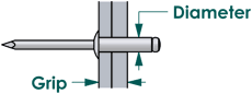
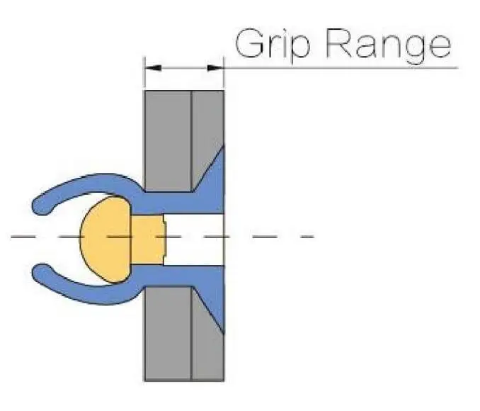
Rivet grip range refers to the range of total material thickness within which a rivet can be correctly installed and securely clamped.
It is defined by the minimum and maximum grip thicknesses.
Minimum Grip and Maximum Grip
The minimum grip range refers to the minimum total material thickness at which the rivet can be properly installed, while the maximum grip range refers to the maximum total material thickness at which it can form a reliable connection.
For example: Grip Range: 1.5–4.0 mm
This indicates that the rivet is suitable for joining materials with a total thickness between 1.5 mm and 4.0 mm. The actual total thickness of the materials being joined must not be less than 2.0 mm, nor should it exceed 4.0 mm.
Why Grip Range Matters in Riveted Joints
1. The grip range determines whether the backside bulb forms correctly.
2. The grip range affects whether the sheets are securely clamped.
3. The grip range influences the fit between the rivet head and the workpiece.
4. The grip range affects the stability of the joint’s load-bearing performance.
5. The grip range influences the mandrel’s break-off process.
6. An incorrect grip range increases the risk of deformation in thin sheets.
7. The grip range affects the consistency of mass assembly.
Rivet Grip Range Vs Rivet Length
| Comparison Item | Rivet Grip Range | Rivet Length |
|---|---|---|
| What It Means | The range of total material thickness that can be reliably joined | The length of the rivet body itself |
| Whether It Is a Range | From minimum value to maximum value | A single size |
| Whether It Is Directly Used to Select Thickness | Yes | Cannot be used alone for selection |
| Whether It Includes Forming Allowance | Considered in the design and testing | Includes the gripping portion and the length needed for rear-side forming |
| Common Marking Format | 1.5–3.0 mm | 10 mm, 12 mm, or 16 mm |
| Selection Basis | Actual total assembled thickness | Used to identify rivet specifications |
Why Rivet Length Is Not the Same as Grip Range
Rivet length refers to the dimension of the rivet body itself, measured from the underside of the rivet head to the end of the body.
The grip range is the range of total material thickness that the rivet can reliably join. This range is determined not only by the rivet body length but also by the rivet’s design and material.
The riveting range of the rivet is less than the length of the rivet body.
How to Measure Rivet Grip Range
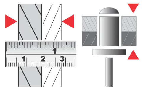
1. Determine the specific riveting location to be measured
The clamping thickness must be measured at the actual rivet hole location; measuring the edge of the sheet material is not acceptable. Components that do not fall within the rivet’s clamping zone should not be included in the clamping thickness calculation.
2. Sum the thicknesses of all materials to be clamped
Actual clamping thickness = Thickness of Sheet 1 + Thickness of Sheet 2 + Thickness of Bracket + Thickness of Shim
3. Measure the total thickness directly after assembly
If the components are already stacked and accessible from both sides, a vernier caliper can be used to directly measure the distance between the outer surfaces at the riveting location.
How to Calculate Rivet Grip Range
Assume that an assembly consists of the following components:
| Component | Nominal Thickness | Thickness Tolerance |
|---|---|---|
| Panel | a mm | ±x mm |
| Bracket | b mm | ±y mm |
| Reinforcement Plate | c mm | ±z mm |
| Compressed Sealing Gasket | d mm | ±w mm |
Nominal total thickness: a + b + c + d = Tₙ mm, where Tₙ = nominal total thickness
Minimum total thickness: (a – x) + (b – y) + (c – z) + (d – w) = Tₘᵢₙ mm, where Tₘᵢₙ = minimum total thickness
Maximum total thickness: (a + x) + (b + y) + (c + z) + (d + w) = Tₘₐₓ mm, where Tₘₐₓ = maximum total thickness
Therefore, the grip range of the selected rivet must fully cover the range: Tₘᵢₙ – Tₘₐₓ mm
Rivet Grip Range Chart
Select a rivet whose grip range fully covers the actual total thickness of all materials being joined.
| Rivet Diameter | Rivet Size | Nominal Body Length | Grip Range |
|---|---|---|---|
| 2.4 mm (3/32 in) | 2.4 × 4.0 mm | 4.0 mm | 0.5–2.0 mm |
| 2.4 × 6.0 mm | 6.0 mm | 2.0–4.0 mm | |
| 2.4 × 8.0 mm | 8.0 mm | 4.0–6.0 mm | |
| 2.4 × 10.0 mm | 10.0 mm | 6.0–8.0 mm | |
| 2.4 × 12.0 mm | 12.0 mm | 7.0–9.5 mm | |
| 2.4 × 14.0 mm | 14.0 mm | 8.0–11.5 mm | |
| 2.4 × 16.0 mm | 16.0 mm | 10.0–13.0 mm | |
| 3.0 mm (7/64 in) | 3.0 × 6.0 mm | 6.0 mm | 1.0–3.5 mm |
| 3.0 × 8.0 mm | 8.0 mm | 3.5–5.0 mm | |
| 3.0 × 10.0 mm | 10.0 mm | 5.0–7.0 mm | |
| 3.0 × 12.0 mm | 12.0 mm | 7.0–9.0 mm | |
| 3.0 × 14.0 mm | 14.0 mm | 9.0–11.0 mm | |
| 3.0 × 16.0 mm | 16.0 mm | 9.0–12.5 mm | |
| 3.0 × 18.0 mm | 18.0 mm | 12.0–14.5 mm | |
| 3.0 × 20.0 mm | 20.0 mm | 13.0–16.5 mm | |
| 3.2 mm (1/8 in) | 3.2 × 6.0 mm | 6.0 mm | 1.0–3.5 mm |
| 3.2 × 8.0 mm | 8.0 mm | 3.5–5.0 mm | |
| 3.2 × 10.0 mm | 10.0 mm | 5.0–7.0 mm | |
| 3.2 × 12.0 mm | 12.0 mm | 7.0–9.0 mm | |
| 3.2 × 14.0 mm | 14.0 mm | 9.0–11.0 mm | |
| 3.2 × 16.0 mm | 16.0 mm | 9.0–12.5 mm | |
| 3.2 × 18.0 mm | 18.0 mm | 12.0–14.5 mm | |
| 3.2 × 20.0 mm | 20.0 mm | 13.0–16.5 mm | |
| 4.0 mm (5/32 in) | 4.0 × 6.0 mm | 6.0 mm | 1.0–3.0 mm |
| 4.0 × 8.0 mm | 8.0 mm | 3.0–5.0 mm | |
| 4.0 × 10.0 mm | 10.0 mm | 4.0–6.5 mm | |
| 4.0 × 12.0 mm | 12.0 mm | 6.0–8.5 mm | |
| 4.0 × 14.0 mm | 14.0 mm | 7.0–10.5 mm | |
| 4.0 × 16.0 mm | 16.0 mm | 8.0–12.5 mm | |
| 4.0 × 18.0 mm | 18.0 mm | 10.0–14.5 mm | |
| 4.0 × 20.0 mm | 20.0 mm | 12.0–16.0 mm | |
| 4.0 × 25.0 mm | 25.0 mm | 16.0–21.0 mm | |
| 4.0 × 30.0 mm | 30.0 mm | 21.0–26.0 mm | |
| 4.8 mm (3/16 in) | 4.8 × 6.0 mm | 6.0 mm | 1.0–2.5 mm |
| 4.8 × 8.0 mm | 8.0 mm | 2.5–4.0 mm | |
| 4.8 × 10.0 mm | 10.0 mm | 4.0–6.0 mm | |
| 4.8 × 12.0 mm | 12.0 mm | 6.0–8.0 mm | |
| 4.8 × 14.0 mm | 14.0 mm | 8.0–10.0 mm | |
| 4.8 × 16.0 mm | 16.0 mm | 9.0–12.0 mm | |
| 4.8 × 18.0 mm | 18.0 mm | 10.0–14.0 mm | |
| 4.8 × 20.0 mm | 20.0 mm | 12.0–16.0 mm | |
| 4.8 × 25.0 mm | 25.0 mm | 16.0–21.0 mm | |
| 4.8 × 30.0 mm | 30.0 mm | 21.0–25.0 mm | |
| 4.8 × 35.0 mm | 35.0 mm | 25.0–30.0 mm | |
| 4.8 × 40.0 mm | 40.0 mm | 30.0–35.0 mm | |
| 5.0 mm (6/31 in) | 5.0 × 6.0 mm | 6.0 mm | 1.0–2.5 mm |
| 5.0 × 8.0 mm | 8.0 mm | 2.5–4.0 mm | |
| 5.0 × 10.0 mm | 10.0 mm | 4.0–6.0 mm | |
| 5.0 × 12.0 mm | 12.0 mm | 6.0–8.0 mm | |
| 5.0 × 14.0 mm | 14.0 mm | 8.0–10.0 mm | |
| 5.0 × 16.0 mm | 16.0 mm | 9.0–12.0 mm | |
| 5.0 × 18.0 mm | 18.0 mm | 10.0–14.0 mm | |
| 5.0 × 20.0 mm | 20.0 mm | 12.0–16.0 mm | |
| 5.0 × 25.0 mm | 25.0 mm | 16.0–21.0 mm | |
| 5.0 × 30.0 mm | 30.0 mm | 21.0–25.0 mm | |
| 5.0 × 35.0 mm | 35.0 mm | 25.0–30.0 mm | |
| 5.0 × 40.0 mm | 40.0 mm | 30.0–35.0 mm | |
| 6.0 mm (15/64 in) | 6.0 × 8.0 mm | 8.0 mm | 1.5–3.0 mm |
| 6.0 × 10.0 mm | 10.0 mm | 3.0–5.0 mm | |
| 6.0 × 12.0 mm | 12.0 mm | 5.0–7.0 mm | |
| 6.0 × 14.0 mm | 14.0 mm | 7.0–9.0 mm | |
| 6.0 × 16.0 mm | 16.0 mm | 7.0–11.0 mm | |
| 6.0 × 18.0 mm | 18.0 mm | 11.0–13.0 mm | |
| 6.0 × 20.0 mm | 20.0 mm | 11.0–15.0 mm | |
| 6.0 × 25.0 mm | 25.0 mm | 14.0–19.5 mm | |
| 6.0 × 30.0 mm | 30.0 mm | 19.5–24.5 mm | |
| 6.0 × 35.0 mm | 35.0 mm | 24.0–29.0 mm | |
| 6.0 × 40.0 mm | 40.0 mm | 29.0–34.0 mm | |
| 6.4 mm (1/4 in) | 6.4 × 8.0 mm | 8.0 mm | 1.5–3.0 mm |
| 6.4 × 10.0 mm | 10.0 mm | 2.0–4.0 mm | |
| 6.4 × 12.0 mm | 12.0 mm | 3.0–6.0 mm | |
| 6.4 × 14.0 mm | 14.0 mm | 6.0–8.0 mm | |
| 6.4 × 16.0 mm | 16.0 mm | 6.0–10.0 mm | |
| 6.4 × 18.0 mm | 18.0 mm | 8.0–12.0 mm | |
| 6.4 × 20.0 mm | 20.0 mm | 10.0–14.0 mm | |
| 6.4 × 25.0 mm | 25.0 mm | 14.0–18.0 mm | |
| 6.4 × 30.0 mm | 30.0 mm | 18.0–23.0 mm | |
| 6.4 × 35.0 mm | 35.0 mm | 23.0–28.0 mm | |
| 6.4 × 40.0 mm | 40.0 mm | 28.0–33.0 mm |
How to Choose the Correct Rivet Grip Range
Step 1: Calculate the total material thickness at the riveting location.
You should identify all materials being clamped, including brackets, panels, metal shims, sealing gaskets, and other components, then calculate their total thickness.
Step 2: Consider material and assembly tolerances.
You need to consider possible variations in sheet thickness, coatings, gaskets, and stamped structures. When selecting the proper rivet nut, you should ensure that the grip range covers the entire thickness range, rather than only matching the average thickness.
Step 3: Use the grip range chart for the corresponding product series.
Different rivets have different back-side forming methods and may also have different grip ranges; specific riveting range reference charts are available for different rivets.Please refer to the Rivmate catalog for detailed riveting range charts.
Step 4: Properly handle soft materials and gaskets.
When you work with soft materials, you should consider that they may undergo creep, springback, or long-term relaxation after blind riveting. You can verify the gasket compression in advance by conducting sample rivet tests.
Step 5: Do not use longer rivets to compensate for assembly gaps.
The two panels cannot fit together properly due to burrs, warping, misalignment, or excessive gaps. Burrs should be removed, and the flatness of the parts improved.
What Happens If the Rivet Grip Range Is Too Short?
1. Insufficient rivet body length on the reverse side of the workpiece
2. Inadequate clamping of the sheets
3. Undersized or incomplete formation of the bulb on the reverse side
4. Potential premature fracture of the mandrel
5. Rivet head may fail to seat flush against the workpiece
6. Inconsistent actual load-bearing capacity of the joint
What Happens If the Rivet Grip Range Is Too Long?
1. Excessive deformable rivet material remains on the back of the workpiece
2. The sheets may not be properly clamped together
3. Abnormal folding may occur in the bulge on the back
4. The mandrel may break at an abnormal location
5. Thin sheets may suffer from indentation, warping, or pull-through
6. Joint clamping force and load-bearing performance may be inconsistent
7. Sealing performance may be compromised
How Grip Range Affects Rivet Joint Strength
1. A correct grip range facilitates the formation of a complete backside bulb.
Within the correct grip range, a stable backside closure head is formed, allowing the rivet to securely clamp the sheets from both sides.
2. The grip range directly affects tensile strength.
Within the correct grip range, the backside bulb provides sufficient load-bearing surface area. This prevents the bulb from passing through the hole and the rivet from being pulled out of the hole.
3. The clamping span also affects actual shear performance.
If the clamping span is incorrect, the panel is not adequately clamped, and relative sliding of the panel will occur first.
4. Grip range affects the clamping state of the joint.
An incorrect grip range prevents the plates from fitting together properly, leading to joint looseness and instability.
5. The clamping range significantly affects vibration and fatigue life.
An incorrect grip range results in a gap in the sheet material, which leads to a reduction in the joint’s fatigue life following frequent vibration.
Does Rivet Diameter Affect Grip Range?
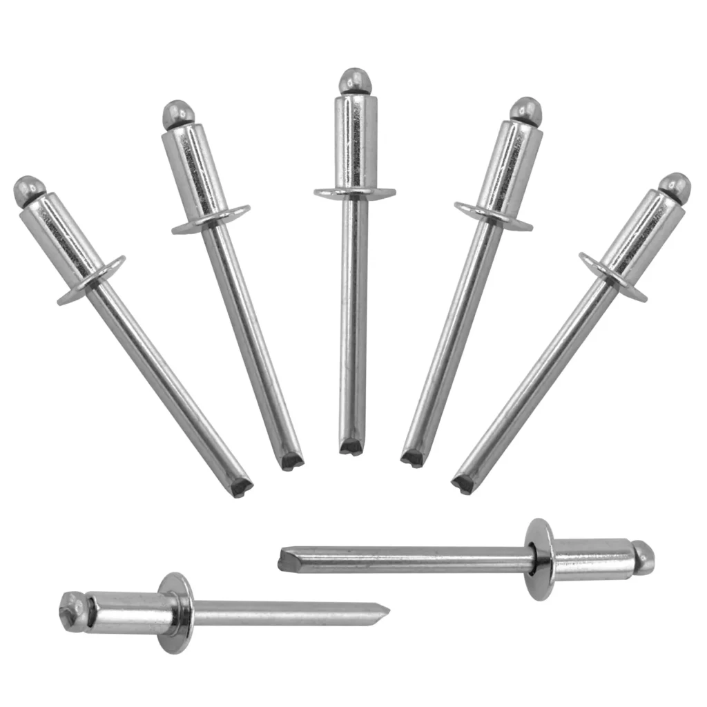
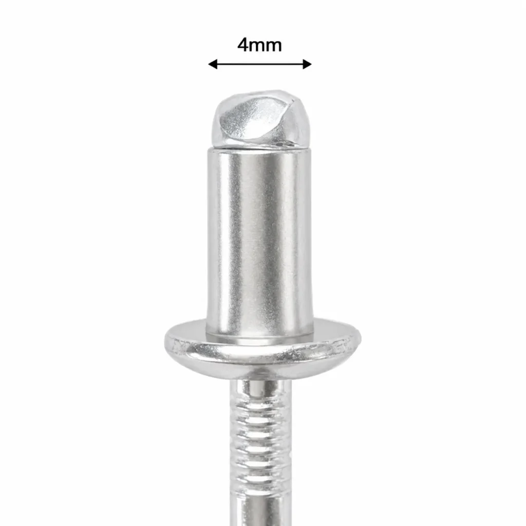
Rivet diameter affects the grip range, but it is not the case that a larger diameter automatically results in a larger grip range.
Changes in rivet diameter alter the dimensions of the rivet body and the mandrel head, as well as the length of the rivet body consumed to form the bulb on the blind side. Given identical rivet body length, material, and structure, a change in diameter alters the length required for back-side formation, thereby changing the range of material thicknesses that can be clamped.
Does Rivet Material Affect Grip Range?
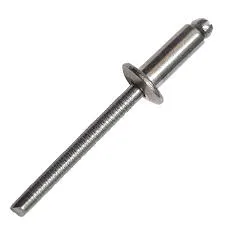
The rivet body material affects the rivet’s deformation, while the mandrel material influences the pulling force required for that deformation. The rivet body material alone does not determine the grip range.
If the rivet body material is softer, it deforms more easily to form a bulb; if the material is harder, a greater pulling force is required.
Does Rivet Head Style Affect Grip Range?
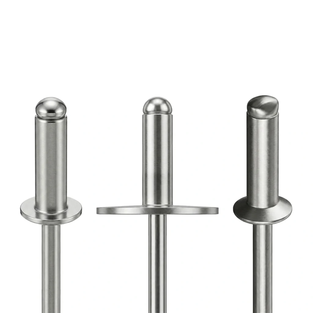
The rivet head style affects the grip range. Round-head and large-flange-head rivets have the least impact, whereas countersunk heads have a more significant effect.
Countersunk rivets feature a tapered head designed to fit into a pre-machined countersunk recess. This alters the position of the rivet’s front-facing bearing surface and shifts the point where force is applied at the front of the rivet. Consequently, even if the rivet diameter and nominal length are identical, the grip ranges for round-head and countersunk models may differ.
Rivet Hole Size and Grip Range
- The hole diameter determines whether the rivet can be correctly inserted, positioned, and fill the installation hole;
- The grip range determines whether the rivet can deform correctly and clamp the workpiece given the total material thickness.
| Hole Size Condition | Grip Range Condition | Possible Problems | Corrective Action |
|---|---|---|---|
Correct Hole Size | Material thickness is within the specified grip range. | The rivet can normally be positioned and formed correctly, allowing the materials to be securely clamped. | Perform a trial installation and inspect the rivet head seating and blind-side formation. |
Hole Too Small | The selected grip range is correct. | The rivet may be difficult to insert. The rivet body or coating may be scratched, and the rivet may become tilted. | Enlarge the hole to the recommended size and remove burrs from the hole edges. |
Hole Too Large | The selected grip range is correct. | The rivet may sit off-center, provide insufficient hole fill or create a loose joint. Shear and vibration performance may become unstable. | Use the hole diameter recommended by the manufacturer. Do not rely on rivet expansion to compensate for an oversized hole. |
Correct Hole Size | Material thickness exceeds the maximum grip. | The rivet is too short. The blind-side head may not form completely, and the materials may not be securely clamped. | Select a rivet with a higher maximum grip capacity. |
Correct Hole Size | Material thickness is below the minimum grip. | The rivet is too long. The body may bend, fold irregularly or form the blind-side head too far away from the material surface. | Select a rivet with a lower minimum grip requirement. |
Both Incorrect | The hole size and the selected rivet grip range are unsuitable. | Insertion difficulty, off-center installation, insufficient clamping and abnormal mandrel breakage may occur. | Reconfirm the required hole size, total material thickness and the specifications of the selected rivet. |
Burrs or Misalignment | The selected grip range is correct. | The rivet head may not seat properly, the rivet body may be scratched, and blind-side formation may become uneven. | Remove the burrs and check the alignment of the holes through all material layers. |
Incorrect Countersink | A countersunk rivet is being used. | The rivet head may sit too high or too low, receive insufficient support, or cause cracking around the hole edge. | Control the through-hole diameter, countersink angle, diameter and depth according to the rivet specifications. |
How to Inspect Rivet Grip After Installation
1. Verify the rivet specifications against the actual material thickness.
2. Check that the rivet head on the front side sits flush against the surface.
3. Ensure the sheets are securely clamped together.
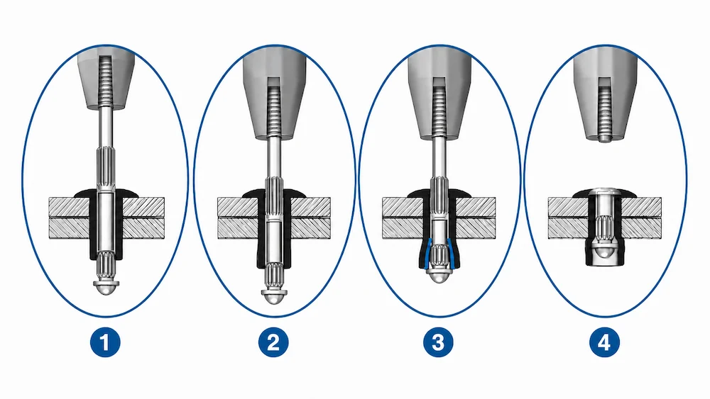
4. Check that the closing head on the back side is correctly formed.
5. Inspect the break point of the mandrel.
6. Check for any damage to the sheets or the rivet holes.
7. Assess whether the rivet is too short or too long based on the formed shape.
8. Conduct dimensional or destructive testing for critical joints.
9. Establish approved sample parts for mass production.
Common Rivet Grip Range Selection Mistakes
| Common Selection Mistake | Possible Consequence | Correct Approach |
|---|---|---|
| Mistaking rivet body length for grip range | The wrong rivet length may be selected. | Check the grip range specified for the exact rivet model. |
| Measuring only one material layer | The actual total material thickness may be underestimated. | Add together the thickness of all materials being clamped. |
| Ignoring material thickness tolerances | Some joints in the production batch may fall outside the allowable grip range. | Calculate both the minimum and maximum total assembly thickness. |
| Assuming a longer rivet is always safer | The rivet body may fold abnormally or fail to clamp the materials securely. | Select a rivet whose grip range covers the actual material thickness. |
| Using a generic grip range chart | The wrong rivet may be selected for a different product series. | Use the technical data for the corresponding rivet series and model. |
| Changing rivet material without rechecking the specifications | The setting behavior and installation tool requirements may no longer match. | Reconfirm the grip range, recommended hole size and installation tool. |
| Checking grip range but ignoring hole size | The rivet may set off-center, remain loose or provide insufficient hole fill. | Verify the manufacturer’s recommended hole size at the same time. |
| Including burrs or assembly gaps in the grip thickness | Underlying fit-up or assembly defects may be concealed. | Improve material fit-up and remove burrs before measuring the total thickness. |
| Accepting the joint only because the mandrel has broken | Incomplete rivet setting or insufficient clamping may go undetected. | Inspect the rivet head seating, blind-side formation and clamping condition. |
| Validating only the average material thickness | The joint may fail at the minimum or maximum assembly thickness. | Validate both the thinnest and thickest assembly conditions. |
How to Choose a Rivet Supplier Based on Grip Range Requirements
- Verify if the supplier can provide comprehensive data on the grip range
- Assess whether the supplier truly understands “total material thickness”
- Ensure the supplier accounts for thickness tolerances rather than relying solely on nominal values
- Check if the product range covers various grip requirements
- Confirm the supplier’s ability to verify hole diameters
- Request samples and support for trial installations
- Check the supplier’s capability to ensure consistent grip performance
- Confirm compatibility with installation tools
- Verify customization capabilities for special grip requirements
- Check documentation, labeling, and batch traceability capabilities
Information Required for a Rivet Grip Range Recommendation
| Information Category | Information to Provide |
|---|---|
| Material Thickness | Nominal, minimum and maximum total assembly thickness |
| Material Stack-Up | Material, thickness and assembly order of each layer |
| Installation Hole | Hole diameter, tolerance, manufacturing method and burr condition |
| Rivet Requirements | Preferred rivet diameter, head style, rivet type and material |
| Joint Performance | Tensile, shear, vibration and fatigue requirements |
| Operating Environment | Corrosion, temperature, sealing and indoor or outdoor conditions |
| Installation Conditions | Tool model, available space, installation cycle time and automation requirements |
| Project Documentation | Drawings, photographs, samples and details of existing problems |
| Commercial Information | Sample quantity, bulk purchasing demand and documentation requirements |
Rivmate Blind Rivet Grip Range Solutions
1. Standard open-end rivets: Suitable for standard sheet thickness connections
2. Multi-Grip and Uni-Grip: Address variations in sheet thickness
3. Sealed blind rivets: Combine grip range with a sealed structure
4. Trifirm and load-spreading rivets: Suitable for thin sheets or soft materials
5. Structural blind rivets: For high-load and high-vibration connections
6. Match materials and surface requirements based on head style
| Head Style | Main Application | Grip Range Selection Considerations |
|---|---|---|
| Dome Head | General industrial fastening applications | Select the grip range according to the total material thickness and the specifications of the exact rivet model. |
| Large Flange | Thin sheets, soft materials or applications requiring a larger front-side bearing area | A larger flange does not mean that the rivet has a wider grip range. |
| Countersunk Head | Applications requiring a flush surface after installation | Confirm the countersink angle, countersink depth and front-sheet thickness together with the specified grip range. |
Frequently Asked Questions About Grip Range for Rivets
Can I Use a Rivet Below Its Minimum Grip?
No.
If the grip range is below the minimum, an excessive amount of the rivet body will protrude from the blind side. This can lead to issues such as improper blind-side formation, insufficient clamping, and unstable joint performance.
Can I Use a Rivet Above Its Maximum Grip?
No.
If the maximum grip range is exceeded, the rivet length is insufficient. The deformable length of the rivet body is inadequate to form a complete closing head on the back side, ultimately compromising the stability of the joint.
Should Material Thickness Be in the Middle of the Grip Range?
It does not necessarily have to be the midpoint value; as long as it falls within the Grip Range, it is acceptable. It will function correctly whether the setting is close to the minimum or maximum grip.
Do Multi-Grip Rivets Cover More Material Thicknesses?
Yes, multi-grip rivets can accommodate a wider range of material thicknesses.
They allow a broader range of sheet thickness requirements to be covered with fewer specifications. This helps reduce the number of rivet SKUs, simplifies inventory management, and minimizes the risk of selecting the wrong size during assembly.
Conclusion: How to Select the Correct Grip Range for Rivets
The rivet’s grip range determines whether the rivet body deforms correctly to clamp the material securely against the rivet head.
The grip range is not determined solely by the rivet length; selecting the correct grip range requires matching it with the appropriate hole diameter, rivet structure, material, head style, and installation tool.
Selecting the correct grip range:
1. Identify all material layers to be clamped;
2. Calculate the total nominal material thickness;
3. Calculate the minimum and maximum total thickness, accounting for tolerances;
4. Determine the rivet type, diameter, material, and head style;
5. Consult the grip range specifications for the specific product model;
6. Confirm that the grip range covers the entire thickness span;
7. Verify the recommended hole diameter, installation tool, and blind-side clearance;
8. Perform test installations using the minimum and maximum thickness conditions;
9. Inspect the head seating, blind-side formation, and joint performance.
Work with a IATF 16949 Certified Blind Rivet Manufacturer
Get High Quality Rivets Instead of Huck and Avdel Rivets

Rivmate Rivet
Rivmate is one of top 3 blind rivets manufacturers in china. The company is IATF 16949 certified and offers high-strength structural blind rivets that serve as alternatives to Huck and Avdel products.
Explore Rivmate Cases

Rivmate Rivet
Rivmate is one of top 3 blind rivets manufacturers in china. The company is IATF 16949 certified and offers high-strength structural blind rivets that serve as alternatives to Huck and Avdel products.

Hey There, I'm Allen!
I am the founder of Rivmate. For over two decades, we have specialized in the manufacture of blind rivets, providing our customers with reliable riveting solutions. Need riveting services? Feel free to contact us.