What is the Difference Between Countersunk Rivets and Regular Rivets? – Rivmate Expert Guide
Table of Contents
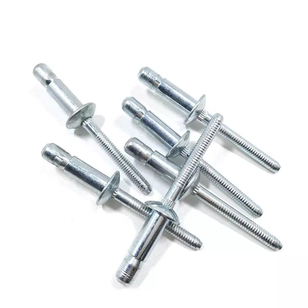
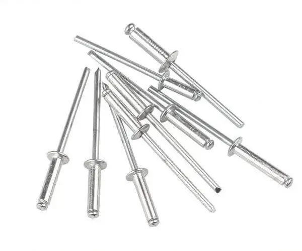
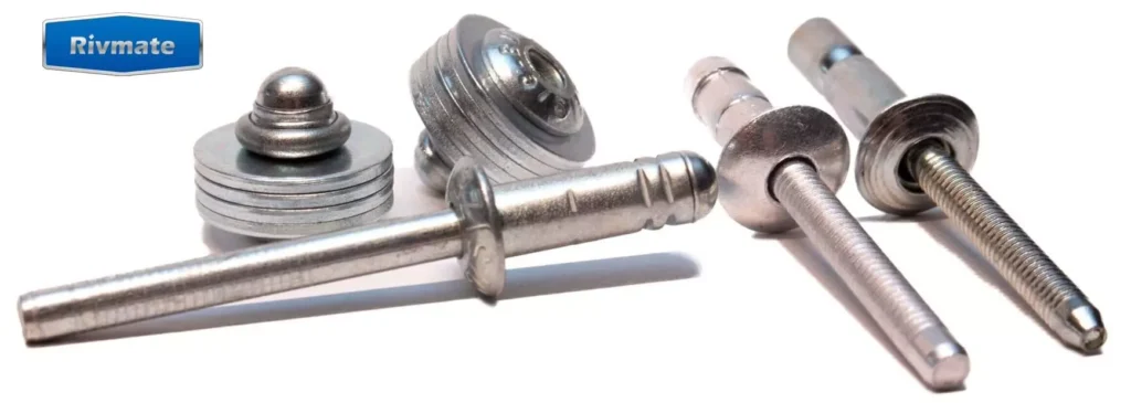
In practical engineering applications, the difference between countersunk rivets and regular rivets (the distinction between countersunk rivets and regular rivets) often becomes a concern for selection personnel and engineers. This is not only related to the structural form of the rivets themselves, but also directly affects the assembly appearance, stress performance, and maintenance efficiency in the future. Countersunk blind rivets and regular blind rivets are common types of Blind Rivets. Although there are obvious differences in appearance, they each have their own advantages in different usage scenarios.
Blind Rivets play a crucial role in modern manufacturing, especially in assembly scenarios where operations can only be performed from one side. These rivets can achieve a secure connection without the need to apply force from the back. They are the preferred fastening method for enhancing assembly efficiency. This article aims to provide clear technical references for product design, process planning, and procurement evaluation.
Basic Definitions and Structural Characteristics
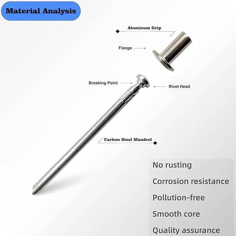
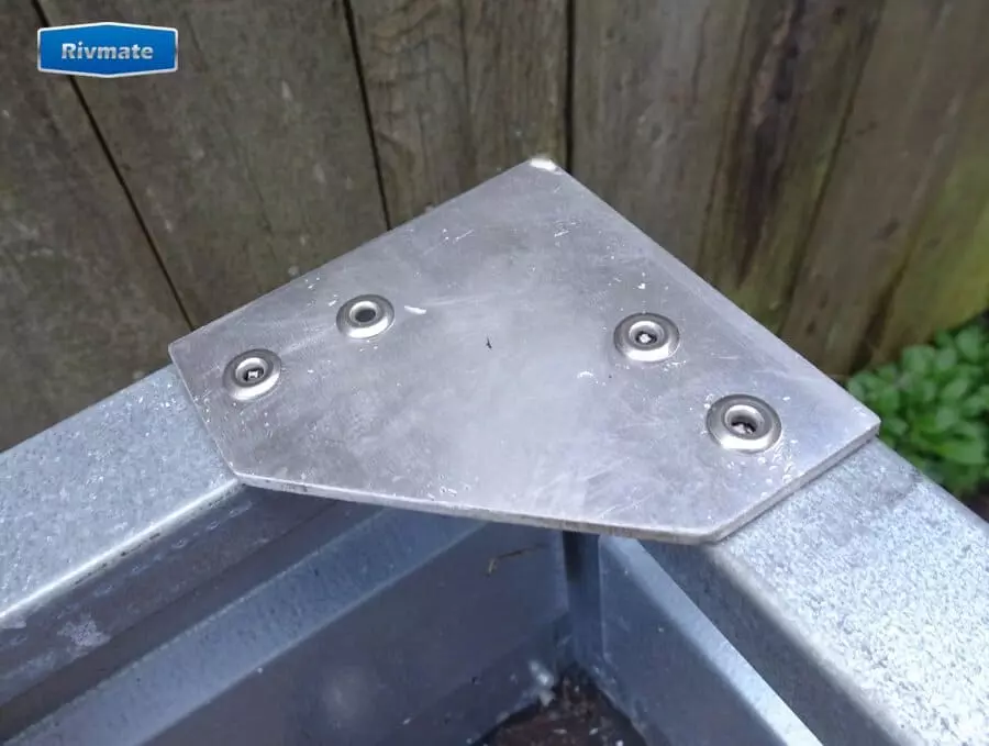
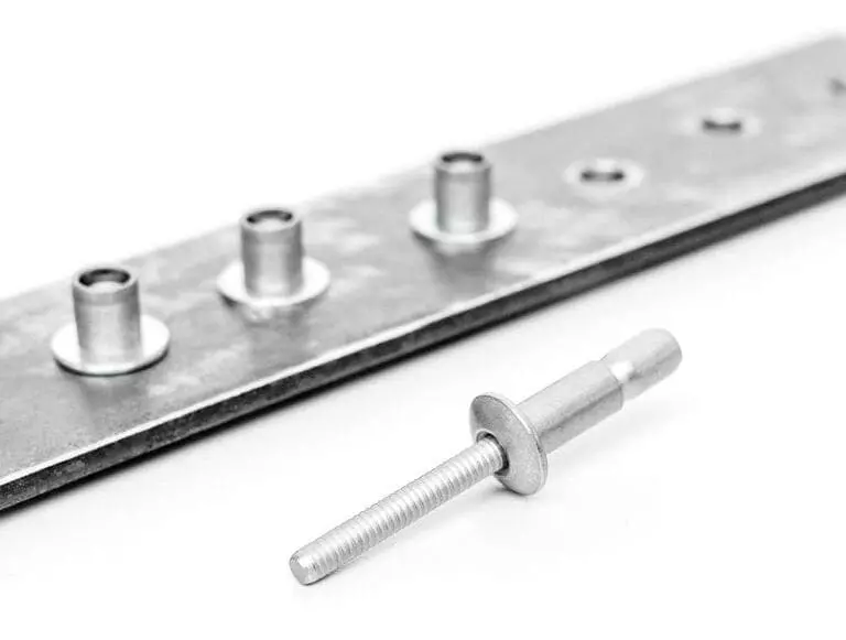
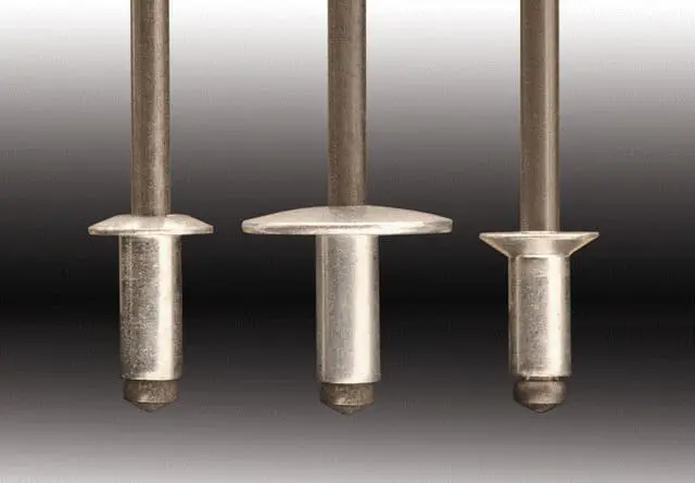
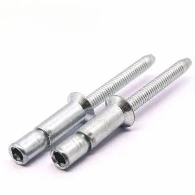
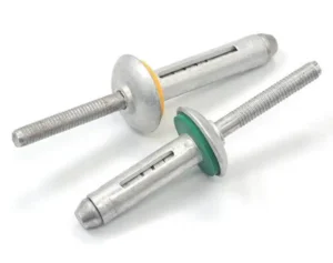
The head of the countersunk rivet is of conical design. After installation, the head can be flush with the surface of the workpiece. A conical countersunk hole needs to be pre-drilled on the workpiece. This structure can effectively improve the flatness of the finished product’s appearance, and is particularly suitable for situations where surface smoothness is required. It is commonly used to reduce air or water resistance, such as in aircraft skins, ship hulls, or high-end equipment covers. Additionally, the flat structure also helps to reduce the risk of scratches and improve the safety of use.
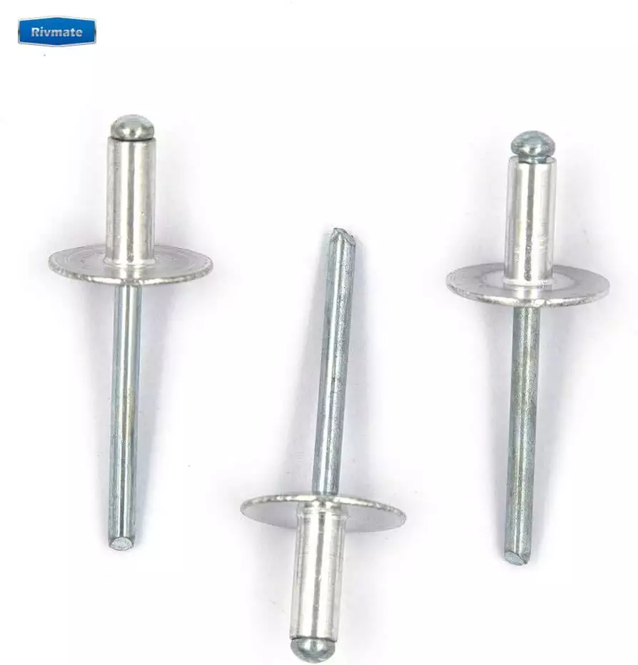
Regular Blind Rivets
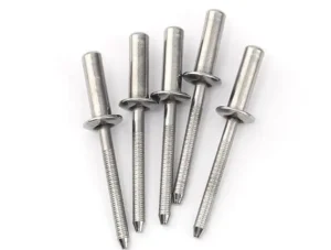
The heads of conventional rivets are mostly round or large cap-shaped, and they are clearly exposed after installation. Compared with countersunk rivets, their installation process is simpler. No need to drill a deep hole; only a standard round hole is required. Due to the exposed rivet heads, the contact surface is larger, making them suitable for connecting structural components with high requirements for anti-tension performance. Such rivets are commonly found in mechanical structures, equipment frames, and industrial products with low requirements for appearance. The emphasis is on structural strength and reliability.
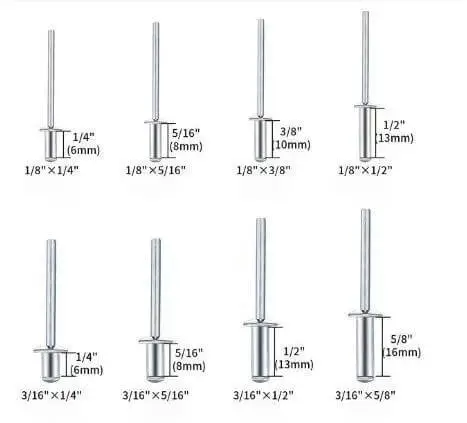
Core Structure and Installation Differences
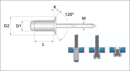
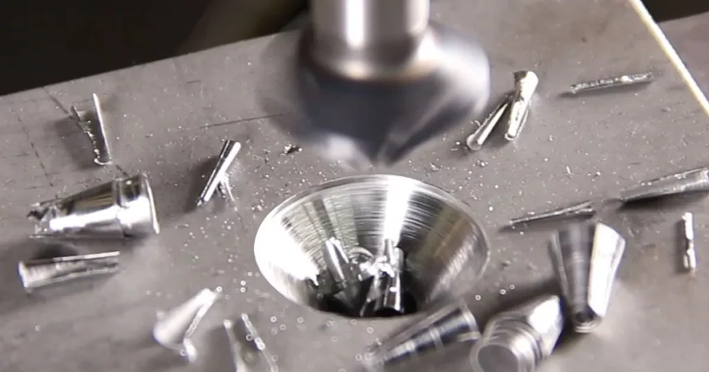
Before installation, Countersunk Blind Rivets require the processing of conical blind holes in the sheet material. This process has higher requirements for the accuracy of the angle and depth of the holes. Inaccurate blind holes can cause the rivets not to be flush, affecting the structural integrity and appearance. On the other hand, Regular Blind Rivets do not require any special pre-treatment. They can be installed with only standard round holes and are suitable for batch operations and ordinary workstation operations.
Although the two types of rivets show no difference when used on the “Blind Rivet Tools“, countersunk rivets require an additional pre-treatment process, making the overall installation procedure slightly more complex. This may affect the assembly cycle, especially when large-scale production is involved, where processing efficiency and cost investment need to be considered.
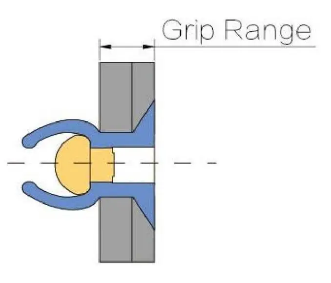
In terms of clamping capability, both have their own grip range. However, it is particularly important to ensure the precise matching of the total thickness of the sheet material and the selection of the rivets. If the countersunk rivets are not selected appropriately, it may cause the depth of the countersunk hole to not match the length of the rivet, thereby affecting the clamping force and the quality of the riveting.
From the perspective of force application, conventional rivets have a larger head surface, which can disperse more loads and reduce the surface stress per unit area. Therefore, they are suitable for withstanding large pulling loads. Although countersunk rivets have better appearance and fluid dynamics, their load distribution is relatively concentrated locally. When selecting the structural type, it is necessary to make a judgment based on the actual load conditions.
Countersunk Rivets VS Regular Rivets: Performance Comparison Table
| Feature / Property | Countersunk Blind Rivets | Regular Blind Rivets |
| Head Profile | Flush with surface | Protrudes above surface |
| Required Hole Prep | Needs countersinking | Standard drilled hole only |
| Aerodynamic/Hydrodynamic | Better (reduced drag) | Less aerodynamic |
| Aesthetic Appearance | Sleek, seamless | Visible head |
| Load Distribution | Smaller bearing area | Larger bearing area |
| Installation Complexity | Higher (extra machining step) | Lower |
| Typical Applications | Aerospace, automotive panels, marine hulls | General sheet metal, construction, machinery |
Difference Between Countersunk Rivets and Regular Rivets in Application Scenarios

a. Countersunk Blind Rivets Common Applications
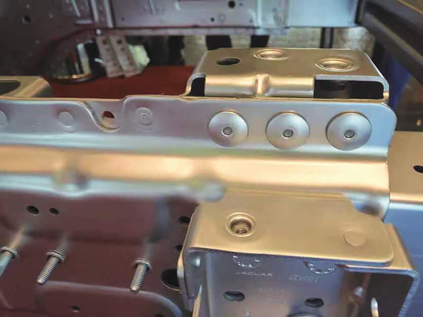
Head-down blind-hole rivets are mainly used in product structures where there are requirements for surface flatness or aerodynamic performance. Their flush installation effect not only enhances the overall design sense but also reduces resistance in dynamic environments, and has a high degree of engineering adaptability.
- Aerospace fuselage skins and wing structure: The aircraft skins must be highly smooth. Self-tapping rivets can prevent surface protrusions, reducing air turbulence during flight and improving fuel efficiency.
- High-performance racing cars and motorcycle shells: During high-speed driving, any protrusions may increase wind resistance or cause structural interference. Self-tapping rivets effectively reduce the turbulence of the shell by concealing the rivet heads.
- Ship decks and yacht outer plates connection: It can avoid local pressure concentration points caused by water flow impact, and at the same time reduce the corrosion risk of connection parts due to long-term water flow.
- High-end electronic device shells: Such as laptop and instrument panels, metal shells often adopt self-tapping designs to enhance the finished product’s craftsmanship and reduce discomfort or scratches for users when contacting the equipment.
The common feature of these fields is that there are high requirements for the synergy of structural integrity, aesthetics and performance, and they are suitable for headless rivets to exert their structural advantages.
b. Regular Blind Rivets Common Applications
The conventional blind rivets emphasize ease of installation, structural strength and versatility, and are widely used in industrial manufacturing, building assembly and daily equipment maintenance.
- Sheet metal structure, ventilation ducts, equipment supports: The rivet installation is quick, suitable for large-scale and low-cost operations. The structure has good stability and can withstand vibrations and loads during normal use.
- Building curtain walls, metal furniture: The large-capacity design can effectively distribute loads, enhance connection strength, and reduce structural stress concentration caused by metal deformation.
- Mechanical manufacturing and maintenance fields: In maintenance sites or structures where pre-processing is not possible, conventional rivets do not require counterboring processing, making it convenient for on-site rapid reinforcement or replacement.
Such applications typically focus on function first, with relatively low requirements for appearance. They emphasize the durability and operational efficiency of riveting, and are the standard configuration options for most industrial products.
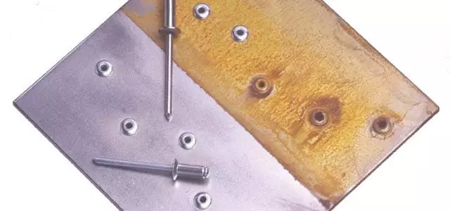
Comparison of Materials and Corrosion Resistance
When discussing the difference between countersunk rivets and regular rivets, apart from the structural and installation differences, the choice of materials also directly affects the service life and applicable environment of the rivets. The corrosion resistance of different substrates determines the reliability of the rivets in marine, outdoor or industrial settings.
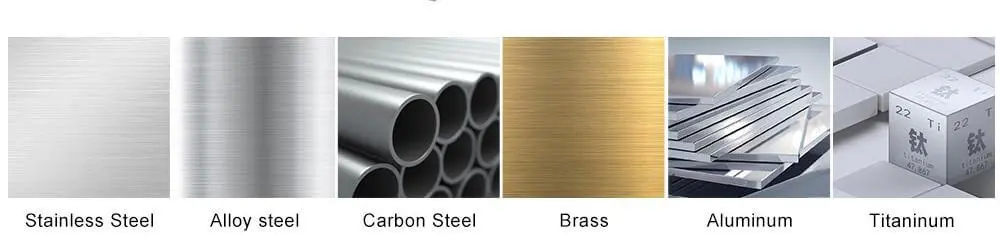
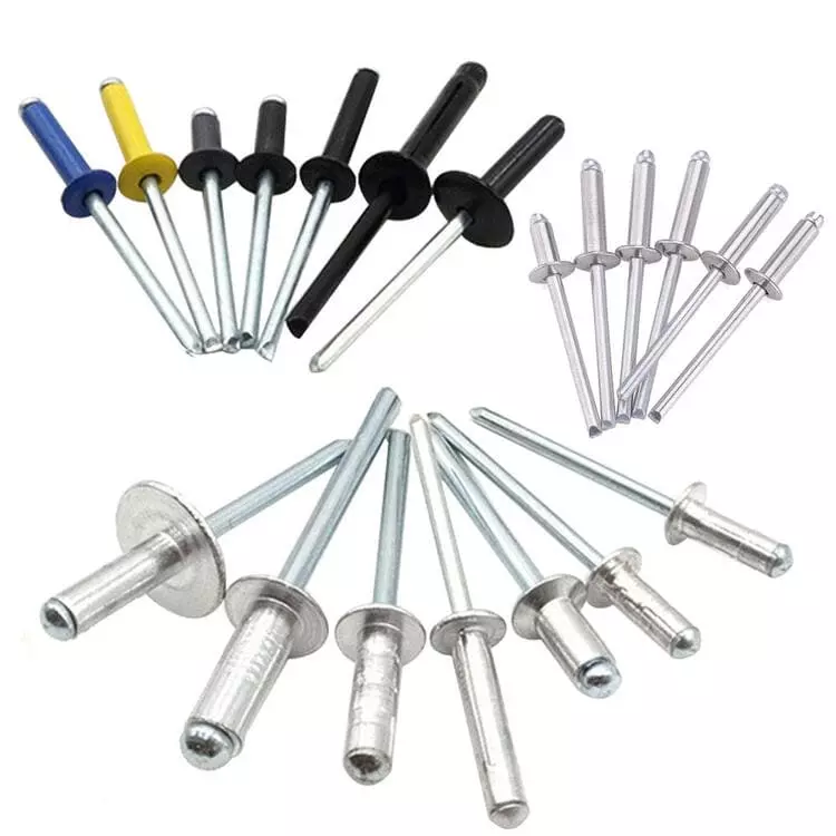
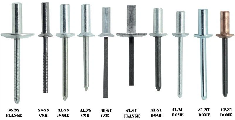
Both types of rivets support various material combinations, which are commonly:
- All-Aluminum: Lightweight, suitable for general indoor and well-ventilated environments, easy to install, and low in cost.
- SS/SS (Stainless Steel): Extremely corrosion-resistant, suitable for high-humidity and high-salt environments, such as coastal facilities or chemical equipment assembly.
- Steel/Steel: High in strength, suitable for load-bearing structures, but requires a protective coating to prevent rusting.
- Copper/Copper: Excellent electrical conductivity, commonly used in electrical equipment and certain decorative structures.
In the Countersunk and Regular types, different materials of rivets can be selected according to the requirements. Countersunk rivets are often combined with stainless steel or aluminum to ensure both appearance and strength. Regular rivets, on the other hand, are more commonly made of steel or aluminum to control costs and enhance structural stability.
② Environmental Adaptability and Corrosion Resistance Properties
The adaptability of different materials to the environment varies significantly:
- In oceanic or highly saline environments, stainless steel or aluminum rivets are the preferred choice. Steel is prone to corrosion and, without special treatment, it is highly susceptible to rusting.
- In outdoor structures, it is recommended to use aluminum or galvanized steel rivets, supplemented by anti-corrosion coatings, to extend their service life.
- In industrial environments (high humidity, chemical exposure), 316-grade stainless steel should be selected to resist acid and alkali erosion as well as moisture corrosion.
The average lifespan of stainless steel core-pulling rivets in marine environments can reach over 10 years. However, if ordinary carbon steel rivets are not treated, red rust and failure may occur within 2-3 years.
③ The anti-corrosion solution provided by Rivmate
As a professional provider of riveting solutions, Rivmate offers a variety of anti-corrosion coatings and customized material services. Including:
- Coating-based anti-corrosion treatment (such as Dacromet, zinc-nickel alloy)
- Mixed-material rivets (such as aluminum cap + stainless steel core)
- Customized for specific purposes, such as electrochemical corrosion-resistant rivets
These services not only extend the service life of the rivets in harsh environments, but also help customers achieve a balance between lightweight and durability, optimize the structural design and reduce maintenance costs.
Recommendations for Model Selection: How to Make a Decision Between the Two Options
In actual projects, the core value of understanding the difference between countersunk rivets and regular rivets lies not in the theoretical distinctions, but in how to make precise selections based on specific application scenarios. The following are common decision-making dimensions and suggestions:
High requirements for appearance and aerodynamics → Choose Countersunk Blind Rivets
If the product surface needs to remain extremely flat, be aesthetically pleasing, or meet fluid dynamics performance requirements, such as for aircraft skins, racing car exteriors, yacht panels, etc., the countersunk blind-hole rivets should be given priority. Their embedded rivet head structure can be flush with the surface of the panel, effectively reducing wind resistance, water resistance or mechanical interference, and enhancing the overall design sense and performance.
Furthermore, in high-end consumer electronics or display devices, the under-cut design can enhance the brand’s quality, reduce contact friction, and improve the user experience.
Prioritize load-bearing capacity and installation efficiency → Choose Regular Blind Rivets
If the project prioritizes structural strength, construction efficiency or assembly cost, conventional pilot-hole rivets have an advantage. Their heads are large, and the force is distributed evenly, making them suitable for supporting loads or connections with high seismic requirements. Moreover, there is no need for a countersink process, significantly reducing the processing difficulty and making them suitable for mass installation and multi-station operations.
In the fields of building metal structure fabrication, mechanical maintenance, or equipment reinforcement, conventional rivets are almost the default choice due to their simple process and strong versatility, which can significantly enhance work efficiency and reduce error rates.
Comprehensive Consideration: Cost, Process Capability, Construction Conditions
In many scenarios, the choice is not an either-or situation. The project should comprehensively evaluate the following factors:
- Budget Constraints: Head screws usually have a slightly higher cost and the installation process is more complex;
- Factory Processing Capacity: Whether there is the capability for precise hole drilling and alignment;
- Construction Environment Constraints: Is the site suitable for high-precision assembly and does it require the installation task to be completed quickly?
For the above complex judgments, Rivmate offers an online selection tool, allowing users to conduct precise filtering based on factors such as plate thickness, material, and application scenarios. Additionally, the technical team can provide 1-on-1 selection advice, helping customers balance performance and cost and improving procurement efficiency.
Installation Precautions and Common Errors

Based on a clear understanding of the difference between countersunk rivets and regular rivets, the correct installation process is equally crucial. Even if the selection is appropriate, improper construction operations can still lead to structural failure or rework. The following are common mistakes and precautions for these two types of rivets:
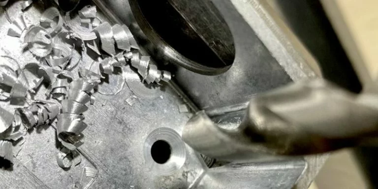
1. Countersunk Bolts: Insufficient Depth of Counterbore
The installation of head-down blind-hole rivets relies on the accurate angle and depth of the blind hole. If the hole is too shallow, it will cause the rivet head not to be fully embedded, resulting in a “bulge” phenomenon, which will affect the appearance and pneumatic performance. In more serious cases, it may lead to “false connection” – the rivet does not actually press against the workpiece but is only supported by the rivet core, presenting a serious structural risk.
It is recommended to use a specialized countersink drill bit and combine it with a depth-limiting device to ensure that the cone angle matches the depth of the hole and the specifications of the rivets. The countersink should be processed in one go to avoid any subsequent rework that may affect the accuracy of the hole position.
2. Regular Rivets: Inappropriate Hole Diameter Matching
The conventional blind rivets have specific requirements for the hole diameter tolerance. If the hole diameter is too large or the burrs are not removed, it will result in reduced clamping force, movement of the rivet, and over time, possible loosening or structural fatigue cracks. It is recommended to refer to the manufacturer’s recommended hole diameter range (usually the rivet diameter plus 0.1 to 0.2 mm) based on the rivet diameter.
At the same time, the rivets should be inserted vertically to avoid uneven loading and to ensure the locking effect.
3. Installation of Tools and Maintenance
The pull pin gun (either manual or pneumatic) is a guarantee for the quality of riveting. If the pulling force is insufficient, it will result in the rivet core not breaking or not being properly pressed; if the pulling force is too large, it may cause local deformation of the sheet material or failure of the rivet due to breakage.、
Furthermore, if the clamping claws are severely worn, a “sliding pin” phenomenon will occur, causing repeated pulling or core jamming. It is recommended to conduct regular inspections and replace the worn parts to keep the tool clean and lubricated.
4. Installation Standard Operating Procedure Recommended by Rivmate Engineers
The Rivmate engineering team, based on extensive field tests and customer feedback, has compiled the following standard operating procedures (SOP):
- Verify that the rivet specifications match the clamping range
- Check the hole diameter and the quality of the blind holes
- Use the appropriate riveting gun and set a reasonable pulling force
- Align the hole position and press it vertically
- Complete the riveting in one go; do not interrupt or repeatedly pull
- Check the condition of the rivet head and confirm that the rivet core has been properly broken
- Clean up the remaining core and the surface burrs to ensure the quality of the finished product
Following the standard procedures not only enhances assembly efficiency, but also significantly reduces the rework rate and safety risks.
FAQs
Will Countersunk Blind Rivets be weaker than Regular Blind Rivets?
Not necessarily. The structural strength depends on several factors: including the material of the rivets, their diameter, the clamping range, and the installation quality. Self-drilling rivets have a smaller contact surface due to their heads being embedded in the sheet, and their bearing capacity under extreme pulling loads may be slightly lower than that of conventional large-head rivets. However, as long as the correct type is selected and installed properly, self-drilling rivets can meet the structural strength requirements in most engineering scenarios. The aviation and racing fields are typical applications of high-strength self-drilling rivets.
Can countersunk rivets be used on plastic or composite materials?
Yes, but special attention should be paid to the strength of the sheet material and the quality of the countersunk holes. Plastics or composite materials are relatively soft, so the countersunk holes are prone to indentation or cracking. It is recommended to use a special drill bit with a low cutting speed and select large-diameter countersunk rivets to distribute the contact pressure. If necessary, metal gaskets or pre-installed metal inserts can be added to the contact surface to enhance the clamping stability. For thin-walled composite materials, sample trial assembly evaluation should be given priority.
Are there any differences in the waterproofing performance between the two?
There are certain differences. Due to the large exposed area of the head of the conventional rivets, when they are combined with sealing gaskets or waterproof rubber rings, it is easier to achieve effective sealing. However, for the countersunk rivets, because of their embedded structure, if the machining accuracy between the blind hole and the rivet is insufficient, a small gap may form, which will affect the sealing performance.
However, this is not absolute. High-quality countersunk holes combined with the application of sealant can also achieve a good waterproofing effect. The actual waterproofing capability depends on the construction process, the sealing material, and the installation quality, rather than just the type of rivets.
Can the countersunk head rivets be replaced with regular rivets after installation?
Generally, direct substitution is not recommended. When installing headless rivets, the sheet material has already been processed into conical holes. If regular round-head rivets are used instead, it will result in uneven contact surfaces, reduced clamping force, and even detachment. Unless the countersunk holes are reamed to a larger size for repair (converted to standard diameters), the structural safety cannot be guaranteed. It is recommended to clearly define the type of rivets during the design stage to avoid the risk of rework caused by on-site replacement.
Choosing the Right Rivet Matters
In engineering structures, the selection of rivet type should be clearly planned during the design stage. This not only affects the appearance and connection performance of the product, but also directly determines the construction efficiency and long-term reliability. Through this analysis, we have systematically compared the structural differences, typical applications, and installation precautions of Countersunk Blind Rivets and Regular Blind Rivets.
A brief overview of the core differences between the two:
- Screw Head Rivet: Suitable for applications with high requirements for appearance, aerodynamics, and smooth contact surfaces; installation requires drilled holes and high processing accuracy.
- Conventional Rivet: Appropriate for connections with heavy structural loads and where construction efficiency is prioritized; no pre-treatment is required and it has strong versatility.
Choosing the right rivets not only improves assembly quality, but also reduces rework rates and maintenance costs.

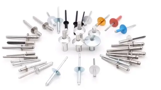
As a supplier of riveting solutions, Rivmate offers a full range of Blind Rivets products, covering multiple material combinations such as aluminum, stainless steel, steel, and copper. Additionally, it provides various anti-corrosion treatment options, including Dacromet, electro-galvanizing, and waterproof type with caps, which are suitable for various extreme working conditions.
More importantly, Rivmate has an experienced application engineering team that can provide a one-stop service ranging from selection guidance, sample testing, to installation process training. We not only sell rivets, but also help customers ensure proper, stable and long-lasting connections.
If you are currently in the stage of product design, procurement or assembly planning, please feel free to contact the Rivmate engineering team for exclusive technical advice and prompt response support.
Reference


What Is the Difference Between Sealed and Unsealed Rivets?
What Is The Difference Be
Are Rivets Waterproof?
Waterproof Rivet –

History of Rivets
History Of Rivets Discove
Closed End Rivets for Aluminum Boat
Closed End Rivets For Alu