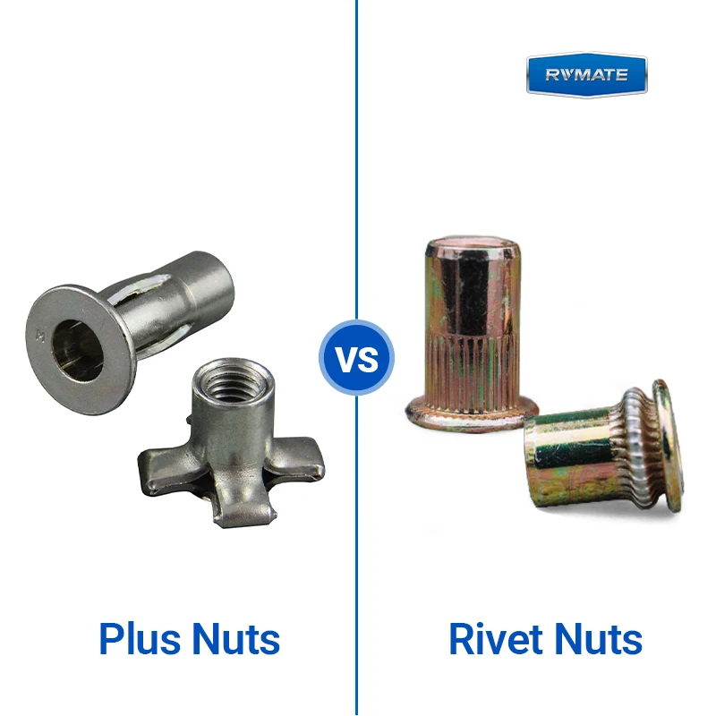
The Plus Nut is a specialized type of rivet nut. The main difference between Plus Nuts and rivet nuts lies in how they deform after installation. They also differ in the way they increase the load-bearing surface area.
The choice between a Plus Nut and a rivet nut depends on the type of sheet metal, sheet thickness, hole diameter, thread specifications, installation quality, and actual load conditions.
Table of Contents
How Slotted Plus Nuts and Conventional Rivet Nuts Expand
Slotted Plus Nuts and Conventional Rivet Nuts operate on the same principle: both use an installation tool to cause plastic deformation at the tail end of the nut, thereby clamping the sheet metal. The difference is that conventional rivet nuts primarily form a locking bulge by expanding outward from the tail end of the body. In contrast, the Plus Nut expands outward through its pre-slotted body to form four independent support legs.
How Conventional Rivet Nuts Expand During Installation
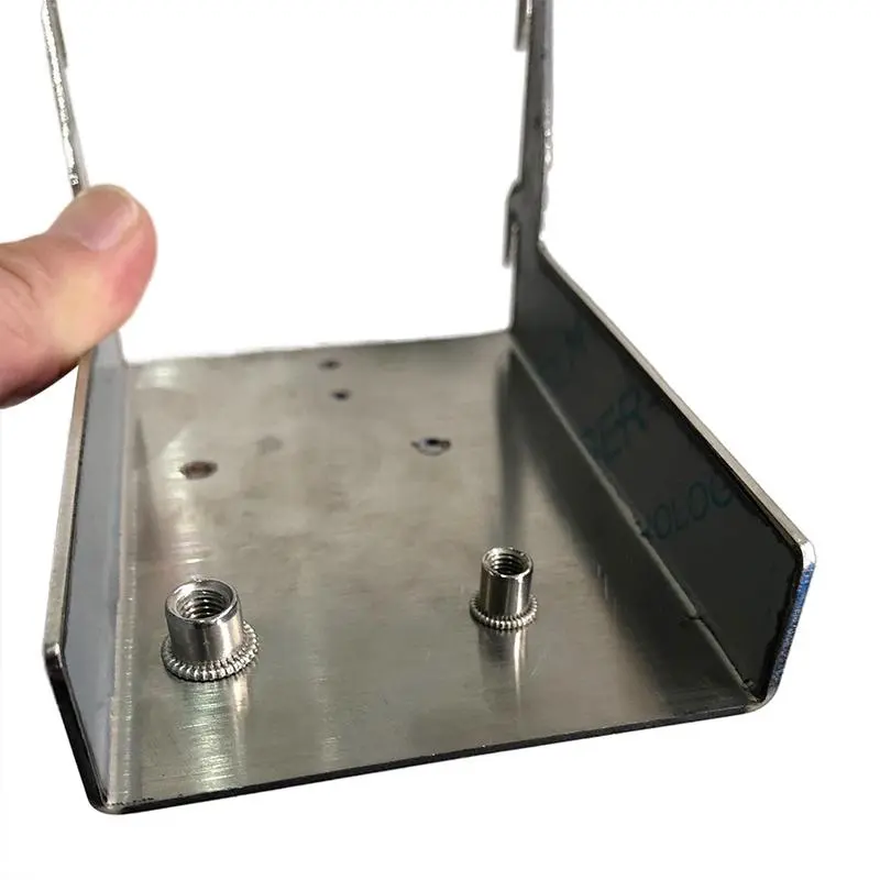
When installing a conventional rivet nut, you must first screw the rivet nut onto the mandrel of the installation tool. When the tool is activated, the mandrel pulls the rivet nut outward. At the same time, the nosepiece at the front of the tool presses against the flange of the rivet nut, creating a counteracting force.
As the mandrel continues to pull outward, the tail end of the rivet nut undergoes axial compression. As the body of the rivet nut gradually shortens, it bulges outward on the back side of the sheet metal, forming a continuous annular bulge.
How Slotted Plus Nuts Expand During Installation
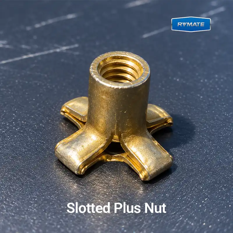
The main difference between Plus Nuts and rivet nuts lies in their body structure. The tail end of a Plus Nut is pre-machined with longitudinal slots.
The installation process for a Plus Nut is similar to that of a standard rivet nut. By pulling the mandrel with an installation tool, the body undergoes axial compression. The difference lies in the fact that the tail end of the Plus Nut has been divided into four longitudinal slots. When the body is compressed, these four support legs bend outward and spread apart individually, ultimately forming a support structure resembling a cross or a four-petaled flower.
Key Differences Between Plus Nuts and Conventional Rivet Nuts
| Installation Stage | How Conventional Rivet Nuts Expand |
|---|---|
| Insert the Rivet Nut | The rivet nut is placed into a pre-drilled hole in the workpiece, with its flange resting against the front surface of the material. |
| Engage the Mandrel | The installation tool’s mandrel engages the internal threads of the rivet nut, while the nosepiece supports the flange. |
| Apply Axial Pulling Force | The tool pulls the mandrel while the nosepiece holds the flange in position, creating an axial compressive force on the rivet nut body. |
| Form the Blind-Side Bulge | The tubular body shortens and undergoes plastic deformation, causing its rear section to expand outward and form a bulb-shaped bulge behind the workpiece. |
| Complete the Clamping | The material is clamped between the front flange and the formed blind-side bulge, securing the rivet nut and providing an internal thread for subsequent bolt installation. |
Choosing for Thin Sheet and Soft Substrates
When fastening thin metal sheets or soft materials, you must decide whether to use a Plus Nut or a Conventional Rivet Nut. The most important factors to consider are whether the base material can withstand the deformation forces during installation and whether it can withstand the pull-out loads exerted by the bolt after installation.
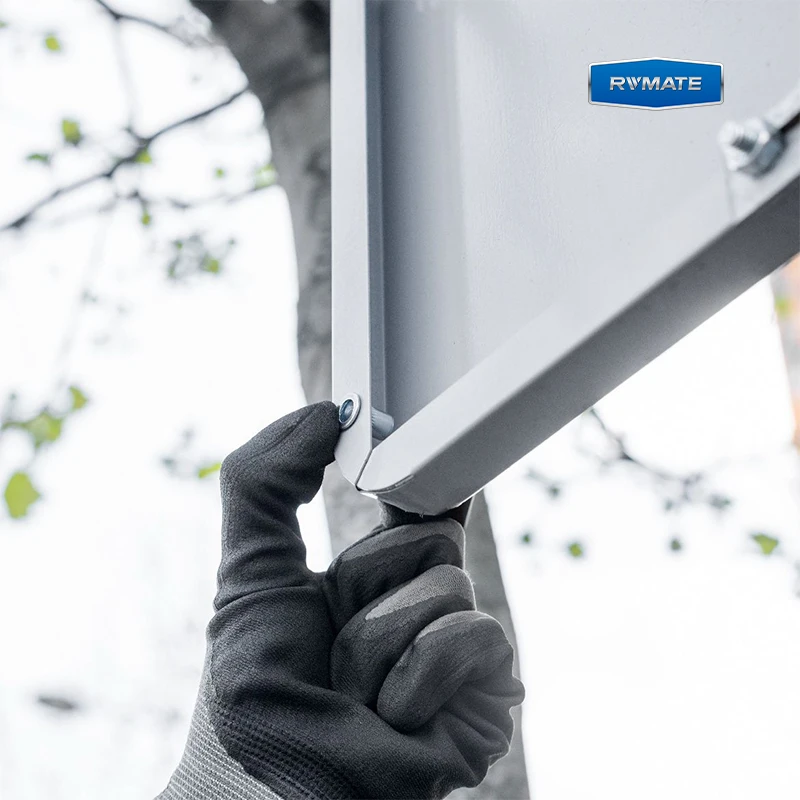
Based on our more than a decade of manufacturing experience, we recommend prioritizing the Slotted Plus Nut for applications involving the fastening of thin sheets and soft materials. The primary reason is that the four expanded support legs formed by the Slotted Plus Nut after installation create a larger load-bearing area on the back of the base material. This effectively distributes the pull-out load over a wider area, reducing the risk of localized stress concentration and deformation.
Some soft materials and thin metal sheets are better suited for rivet nuts. For example, sheets that are thin but possess sufficient rigidity and are subjected to moderate connection loads. We recommend testing the installation of a rivet nut to observe the connection results. If a complete, stable bulge forms on the back side, the rivet nut can be used.
Grip Range, Hole Size, and Blind-Side Clearance
When comparing Plus Nuts and Conventional Rivet Nuts, the grip range, hole size, and blind-side clearance are the three key parameters to consider during selection.
Grip Range, Hole Size, and Blind-Side Clearance directly determine whether the rivet nut can be installed correctly, whether a stable blind-side locking structure can be formed, and whether the final connection will be reliable over the long term. If the selected grip range does not match, the hole size is inappropriate, or there is insufficient space on the back of the sheet metal for the nut to deform, installation failure will result.
Due to differences in their body structures, standard rivet nuts and Plus Nuts do not follow the same selection logic. Because of the differences in their deformation mechanisms, you must pay special attention to the expansion space required by the Plus Nut.
How to Choose the Right Grip Range for Plus Nuts and Rivet Nuts
The grip range refers to the range of base material thicknesses within which a rivet nut can be properly installed and form an effective mechanical lock. For example, if the technical specifications for a particular model of rivet nut list a grip range of 0.5–3.0 mm, this indicates the range of sheet thicknesses it can clamp—not that the nut itself is 0.5–3.0 mm long.
The correct method for testing the grip range is to measure the total actual thickness that needs to be clamped between the flange head and the deformed area on the back. Burrs, bends, coatings, and gaps between different materials on the sheet metal can all affect the actual clamping thickness. You must ensure that the actual material thickness falls within the grip range specified by the manufacturer.
Plus Nuts have a wider clamping range than standard rivet nuts. Taking Rivmate’s M6 carbon steel products as an example, the standard flat-head knurled rivet nut SFKM6-30 has a clamping range of 0.50–3.00 mm, while the SFKM6-55 has a clamping range of 3.00–5.50 mm. In contrast, the grip range for the slotted rivet nut SFTM6-70 is 0.50–7.00 mm, while that for the SFTM6-127 is 7.10–12.70 mm.
Hole Size Requirements for Plus Nuts and Conventional Rivet Nuts
The “Hole Size” refers to the hole pre-machined in the sheet metal prior to installation. The size and quality of the mounting hole directly affect whether the rivet nut can be inserted smoothly and whether a reliable mechanical fastening can be achieved.
The size of the mounting hole is not directly determined by the internal thread specification. Even for M6-sized Plus Nuts and standard rivet nuts, the required blind hole diameters listed in the corresponding specification tables differ. For example, the M6 standard flat-head knurled rivet nut SFKM6-30 manufactured by Rivmate requires a 9.00 mm installation hole, while the M6 slotted rivet nut SFTM6-70 requires a 9.85 mm installation hole. The difference in hole diameter is 0.85 mm.
Blind-Side Clearance Requirements for Plus Nuts and Rivet Nuts
Blind-side clearance refers to the space required behind the mounting hole for the rivet nut to be inserted, deformed, and for the final locking structure to form. Since the Plus Nut forms differently from a standard rivet nut on the back side, you must verify that there is sufficient blind-side clearance based on the specific structure.
- During installation, the tail end of the rivet nut expands outward, forming a protrusion on the back side. The clearance requirements specify sufficient axial and radial space to allow the bulge to form completely.
- During Plus Nut installation, the four support legs must spread outward, forming a large four-lobed support structure on the back side. The clearance requirements not only ensure that the nut’s tail can be inserted but also verify that the four support legs will not come into contact with nearby tube walls, reinforcing ribs, or other internal components when they expand.
Comparing Pull-Out and Spin-Out Test Results
What Does a Pull-Out Test Measure?
The purpose of a pull-out test is to evaluate the ability of a rivet nut to resist axial pull-out after installation. The test involves mounting the rivet nut on a test plate made of a specified material and thickness. A test bolt or specialized fixture is then used to gradually apply axial tensile force until the connection fails, at which point the maximum tensile force is recorded.
What Does a Spin-Out Test Measure?
The purpose of a spin-out test is to evaluate the rivet nut’s ability to resist rotation after installation. The test involves screwing a bolt into the installed rivet nut and gradually increasing the tightening torque using a torque testing device until the rivet nut begins to rotate relative to the base material; the torque value at the onset of rotation is then recorded.
Key Differences Between Pull-Out and Spin-Out Tests
| Comparison Item | Pull-Out Test | Spin-Out Test |
|---|---|---|
| Test Purpose | Measures the ability of a rivet nut to resist axial pull-out from the parent material. | Measures the ability of a rivet nut to resist rotation within the installed hole. |
| Applied Load | Axial tensile force | Rotational torque |
| Test Direction | Along the centerline of the rivet nut | Around the centerline of the rivet nut |
| Main Failure Modes | Parent material tearing, rivet nut pull-out, or thread failure | Rivet nut rotation within the installation hole |
| Key Influencing Factors | Material thickness, material strength, hole diameter, grip range, and blind-side support structure | Body design, knurled or hex body configuration, hole fit, and installation quality |
| Typical Applications | Joints subjected to axial tensile loads | Joints requiring bolt tightening and removal |
How to Interpret Rivet Nut Test Results
| Test Results | Possible Issues | Selection Recommendations |
|---|---|---|
| High pull-out strength, low spin-out resistance | Good axial retention, but insufficient resistance to rotation within the installation hole. | Focus on improving the anti-rotation design or hole fit. |
| Low pull-out strength, high spin-out resistance | The rivet nut resists rotation well, but the parent material may not withstand the axial tensile load. | Reassess the parent material strength and blind-side support structure. |
| High performance in both tests | Both axial retention and anti-rotation performance are satisfactory. | Further verify whether the performance meets actual application requirements. |
| Low performance in both tests | The product design, installation conditions, or parent material may be unsuitable for the application. | Reconsider the product selection and verify the installation parameters. |
Installation Tools, Setting Force, and Repeatability
When installing Plus Nuts or Conventional Rivet Nuts, it is also important to ensure that the tool, die, and pulling force are properly matched. Failure to do so can directly result in insufficient deformation of the rivet nut, damage to the base material, deformation of the internal threads, or even loosening or rotation after installation.
Choose the Right Tool for Each Rivet Nut
Common installation tools include manual rivet nut guns, pneumatic rivet nut guns, electric rivet nut guns, and hydraulic rivet nut installation equipment. The main differences among these tools lie in their power source, output capacity, installation speed, and control methods. You should select the appropriate tool based on the specific requirements of your project.
- Manual tools are suitable for small-batch installations, repairs, and on-site work.
- Pneumatic tools are suitable for production lines requiring continuous installation.
- Electric and hydraulic equipment can adjust installation parameters to varying degrees depending on the specific model.
Force Control vs. Stroke Control for Rivet Nut Installation。
| Comparison Item | Stroke Control | Force Control |
|---|---|---|
| Control Parameter | Mandrel travel distance | Axial installation pulling force |
| Stop Condition | Reaches the preset stroke | Reaches the preset installation force |
| Suitable Applications | Applications with relatively consistent products and material thicknesses | Applications where material thickness varies within a certain range |
| Main Advantage | Easy-to-understand parameters and repeatable installation under fixed conditions | Helps maintain consistent installation results across workpieces of different thicknesses |
| Main Risk | Material thickness variations may cause insufficient or excessive deformation | Incorrect force settings may damage the fastener or parent material |
| Selection Requirement | Determine the stroke according to the product and material thickness | Determine the installation force according to the product’s technical requirements |
How to Ensure Consistent Installation of Plus Nuts and Rivet Nuts
- Step 1: Ensure the parameters for installing rivet nuts are fixed. Standardize and confirm the rivet nut model, base material thickness, installation hole diameter, tool model, and the corresponding installation stroke or installation force.
- Step 2: Maintain consistent quality of the tool’s internal components. Before mass production, you must regularly inspect the mandrel, nozzle, and the tool’s mechanical condition, and perform maintenance and replacements according to the manufacturer’s requirements.
- Step 3: Ensure the installation tool is perpendicular to the sheet metal surface. If the tool is operated at an angle, preventing the flange from making uniform contact with the sheet metal, asymmetrical deformation may occur on the reverse side.
- Step 4: Establish a mechanism for first-article sample trial assembly verification and process inspection. Before mass production, a trial assembly must be performed on actual material to verify that the rivet nuts are in proper condition and function normally after installation. During mass production, random inspections should also be conducted periodically in accordance with the quality control plan.
Matching Each Insert to Van Builds and Equipment Mounts
When to Use Plus Nuts in Van Builds
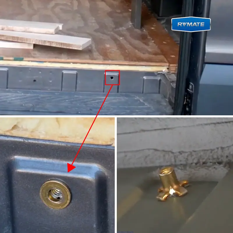
The interior panels of vans are actually made of thin-walled sheet metal and plastic panels, which are not suitable for direct installation of standard rivet nuts. In contrast, the slotted body of the Plus Nut expands into four support legs during installation, increasing the support area on the back of the panel. This distributes the fastening load and effectively addresses the issue of excessive concentrated pull-out stress on the base material. For installation locations that already feature reinforcing ribs, structural brackets, or thicker metal connection areas, the use of standard rivet nuts may be considered.
Suitable Applications:
- Thin-walled sheet metal in van interiors.
- Storage cabinets, tool racks, and interior modules.
- Folding tables and auxiliary brackets.
- Plastic interior panels and composite panels.
When Conventional Rivet Nuts Are Suitable for Equipment Mounts
In equipment mounting applications, when the base material has sufficient rigidity to withstand the pressure generated during the installation of the rivet nut—as well as the torque produced by bolt tightening and the loads generated during equipment operation—selecting a rivet nut is a practical choice.
Suitable Applications:
- Industrial equipment enclosures
- Electrical control cabinets
- Metal mounting brackets
- Equipment mounting plates and auxiliary fasteners
Part Price and Total Installation Cost
| Cost Factor | Plus Nut | Conventional Rivet Nut | What to Compare |
|---|---|---|---|
| Part Price | Depends on material, thread size, grip range, design, and order quantity. | Depends on material, body design, thread size, surface finish, and order quantity. | Compare products with equivalent materials, thread sizes, grip ranges, and performance requirements. |
| Manufacturing and Design | Slotted body construction and expansion-leg design affect manufacturing costs. | Knurled, half-hex, full-hex, and other body designs have different manufacturing requirements. | Consider product geometry, material consumption, manufacturing processes, and specifications. |
| Installation Tooling | May require compatible mandrels, anvils, or dedicated installation equipment. | Can use manual, pneumatic, battery-powered, or hydraulic installation tools, depending on the product. | Check existing tool compatibility and the cost of additional equipment or accessories. |
| Labor and Installation Time | Installation time depends on the product design, tool compatibility, and required setting procedure. | Installation time depends on the product type, tool setup, and production conditions. | Measure actual installation time and labor cost per accepted insert. |
| Setup and Changeover | Different sizes or product series may require compatible tooling and setting adjustments. | Different thread sizes and body designs may require mandrel, nosepiece, or setting changes. | Include tool adjustment, product changeover, and production preparation time. |
| Inventory Cost | Some models offer wider grip ranges, potentially reducing the number of sizes required. | Different grip ranges and body styles may require additional SKUs. | Compare the required product range, minimum order quantities, and inventory levels. |
| Material Damage and Rework | The expanded legs may provide a wider blind-side support area in suitable thin or soft materials. | Performance depends on body design, parent material, hole fit, and installation quality. | Evaluate pull-out failures, spin-out, panel deformation, replacement labor, and scrap costs. |
| Additional Reinforcement | May reduce the need for additional support in suitable applications, subject to load verification. | May require backing plates or reinforcement when the parent material cannot support the design load. | Include reinforcement materials, additional components, and assembly labor where required. |
| Maintenance | Include mandrel, anvil, and installation tool maintenance costs. | Include mandrel, nosepiece, and installation tool maintenance costs. | Consider spare parts, replacement frequency, and equipment downtime. |
| Total Installed Cost | Evaluate the combined fastener, tooling, labor, setup, maintenance, and rework costs. | Evaluate the same cost components under equivalent application requirements. | Compare the total cost per accepted installation, not just the purchase price per insert. |
FAQs
Is a Plus Nut the same as a cross nut?
Yes. A Plus Nut is also known as a Cross Nut.
Can Plus Nuts be installed without a dedicated tool?
Yes. Installation still requires tools that are compatible with the product’s structure, thread specifications, and installation method. Do not use a wrench with a ring attachment for installation.
Can either insert be removed without enlarging the hole?
Yes. Provided that the drilling depth can be properly controlled during the removal process to prevent damage to the borehole walls.
Are Plus Nuts available in stainless steel?
Yes. Plus Nut can be made of stainless steel.
Can a bolt be removed repeatedly from either insert?
Yes. Both Plus Nuts and rivet nuts allow bolts to be repeatedly removed and reinstalled. The actual service life for repeated removal and reinstallation depends on the strength of the internal threads, the product material, the bolt specifications, the tightening torque, and the anti-rotation capability after installation.
Can Plus Nuts be used in an existing rivet nut hole?
Yes. However, certain size requirements and installation conditions must be met. Not all Plus Nuts of the same size can be installed in the original rivet nut holes. You’ll need to compare the diameter, shape, and roundness of the original mounting holes with the hole diameter tolerances specified by the Plus Nut manufacturer.
Do Plus Nuts seal out water?
No. Plus Nut is not a sealing fastener. It cannot prevent water from entering the internal structure.
Are Plus Nuts suitable for mounting seat belts?
Not suitable. Seat belt anchor points are safety-critical connections that must meet strict structural strength requirements. Plus Nut is primarily designed to address load-bearing issues on thin sheets and soft materials.
Work with a IATF 16949 Certified Blind Rivet Manufacturer
Get High Quality Rivets Instead of Huck and Avdel Rivets
Rivmate Rivet
Rivmate is blind rivets manufacturers in china. The company is IATF 16949 certified and offers high-strength structural blind rivets that serve as alternatives to Huck and Avdel products.
Explore Rivmate Cases
Rivmate Rivet
Rivmate is blind rivets manufacturers in china. The company is IATF 16949 certified and offers high-strength structural blind rivets that serve as alternatives to Huck and Avdel products.

Hey There, I'm Allen!
I am the boss of Rivmate. For over two decades, we have specialized in the manufacture of blind rivets, providing our customers with reliable riveting solutions. Need riveting services? Feel free to contact us.