A rivet nut works by being pulled with a riveting tool, causing the tail end of the rivet nut to undergo plastic deformation on the back of the sheet metal, forming a clamping bulge. At the same time, it clamps the sheet metal together with the head of the rivet nut, creating a reliable, secure connection.
The installation process is critical, as it determines whether the rivet nut will be securely installed. Below, I will guide you through the correct installation procedure and explain the factors that influence the process.
Table of Contents
How Rivet Nuts Create a Threaded Joint in Thin Material
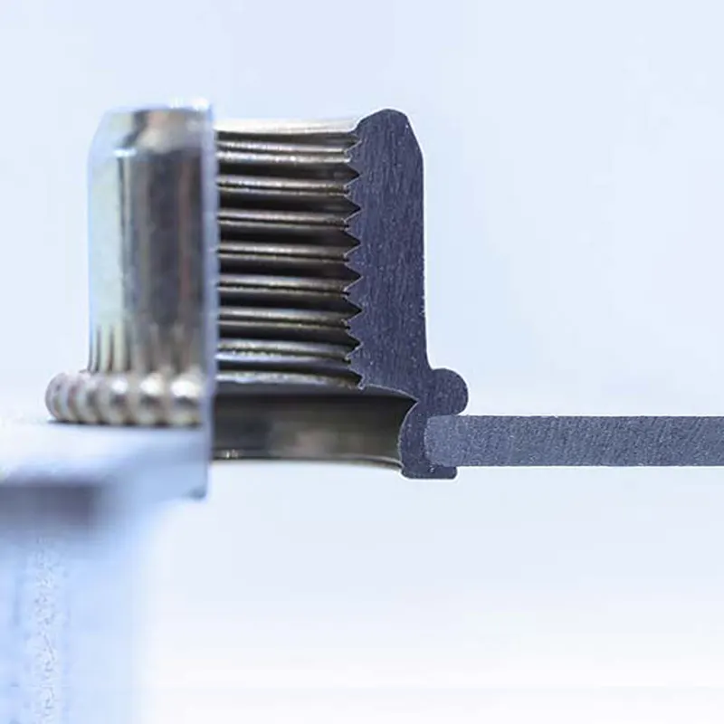
Rivet nuts are pre-machined with internal threads before installation. To install one, you first need to drill a mounting hole that meets the specifications in the thin material, and then use a rivet nut tool to rivet the rivet nut into place.
The front end of the rivet gun has a component called a mandrel, which screws into the internal threads of the rivet nut. When the tool begins operation, the mandrel pulls the rivet nut backward, while the head of the rivet nut is restrained by the tool or the surface of the sheet metal and cannot move with it. The axial pull forces the tail end of the rivet nut to undergo plastic deformation, causing it to bulge outward and form a locking structure on the back side of the material.
Ultimately, the sheet metal is clamped between the head of the rivet nut on the front side and the deformed bulge on the back side. These two parts work together to generate a clamping force that secures the rivet nut within the material. This creates a fixed internal threaded point, allowing subsequent bolts to be repeatedly installed and removed.
What Happens to the Rivet Nut During Installation?

When installing a rivet nut, what actually occurs is plastic deformation of the rivet nut itself. This is because, during installation, the rivet nut is pulled from the inside by the tool, and under the axial tensile force, the thin-walled area at the very bottom undergoes permanent deformation. A bulge forms on the back of the sheet metal, which, together with the head of the rivet nut, clamps the sheet metal in place.
How the Mandrel and Rivet Nut Tool Apply Setting Force
When installing a rivet nut, it is not only the mandrel pulling “backward” on its own that causes the rivet nut to deform, but also the relative movement between the mandrel and the tool’s front support component, which creates an axial load inside the rivet nut.
The mandrel pulls the rivet nut from the inside, while the anvil or nosepiece at the front of the installation tool presses against the head of the rivet nut. When a pneumatic installation tool applies both forces simultaneously, it generates the setting force required for installation.
During installation, the correct procedure is to ensure that the rivet nut is properly screwed onto the mandrel and is in contact with the anvil before riveting, while the head of the rivet nut must lie flat against the surface of the workpiece.
Step-by-Step Rivet Nut Installation Process
Installing a rivet nut is a simple process, but ensuring the stability of the rivet nut connection is more complex. There are many factors that affect the reliability of a rivet nut, including hole diameter, clamping range, tool nozzle, tension, and installation method.Follow our complete rivet nut installation guide for detailed preparation, checking, and troubleshooting steps.
Nine Steps for Properly Installing Rivet Nuts
- Step 1: Verify the rivet nut specifications and clamping range: Before installation, first confirm that the selected rivet nut is suitable for the current sheet metal.
- Step 2: Machine and inspect the mounting hole: The mounting hole must meet the diameter requirements provided by the manufacturer. The diameter of the mounting hole should be slightly larger than the thread size of the rivet nut.
- Step 3: Deburr the holes
- Step 4: Select the correct installation tool and make adjustments: You need to install the appropriate pull rod and support head based on the rivet nut’s specifications.
- Step 5: Screw the rivet nut onto the pull rod: Screw the rivet nut onto the pull rod so that their threads engage correctly.
- Step 5: Fully Insert the Rivet Nut: Pass the rivet nut through all the materials to be joined. The head should sit flush against the surface of the sheet metal.
- Step 6: Keep the Tool Perpendicular to the Sheet Metal Surface: Ensure that the pull rod, rivet nut, and mounting hole are aligned on the same axis.
- Step 7: Activate the Tool to Complete the Riveting
- Step 8: Remove the Pull Rod
- Step 9: Inspect the Installation Quality
How Body Shape Prevents Spinning and Pull-Out
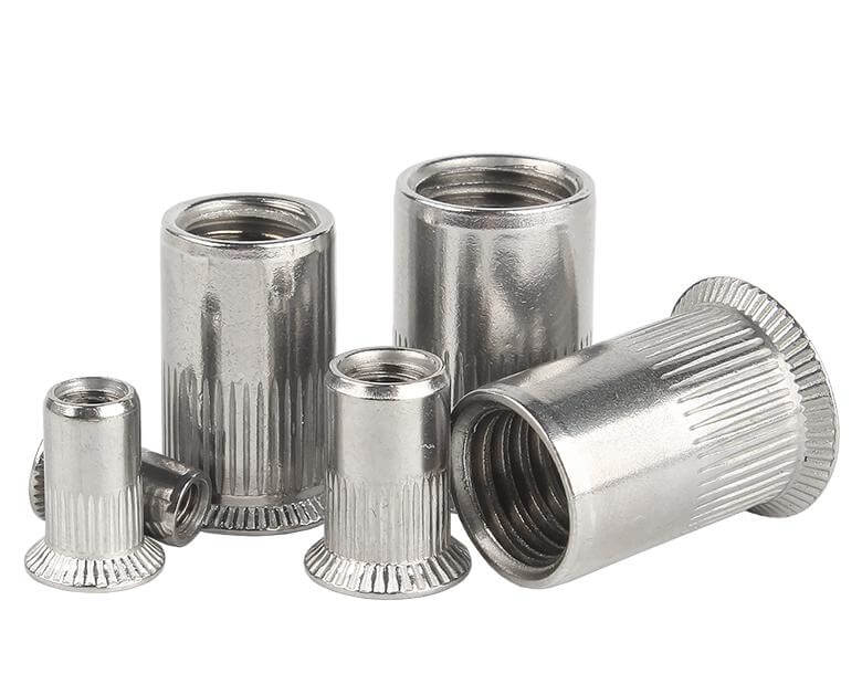
Once a rivet nut is installed, it must not only be secured to the sheet metal but also withstand the torque generated when tightening the bolt, as well as any tensile forces that may occur during use. Therefore, different body structures must be selected to ensure adequate resistance to rotation and pull-out.
- Spin-out refers to the phenomenon where, when tightening or removing a bolt, the rivet nut body rotates along with the bolt inside the mounting hole.
- Pull-out refers to the rivet nut being pulled out of the mounting hole in the sheet metal when subjected to axial tensile force.
Please refer to our rivet nut selection guide to compare options for the body, head, end, thread, and clamping range of rivet nuts.
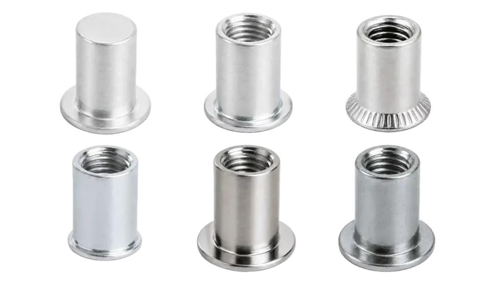
The body has a smooth cylindrical shape and is typically installed in a round hole. Its anti-rotation capability primarily comes from the clamping action after installation and friction at the contact surfaces. It is suitable for standard connections with low anti-rotation requirements.

The outer surface of the body features a knurled pattern. During installation, the knurling engages mechanically with the wall of a suitable hole, thereby enhancing anti-rotation capability. It is suitable for applications where only round holes can be machined. It offers greater anti-rotation resistance than Round Body Rivet Nuts.
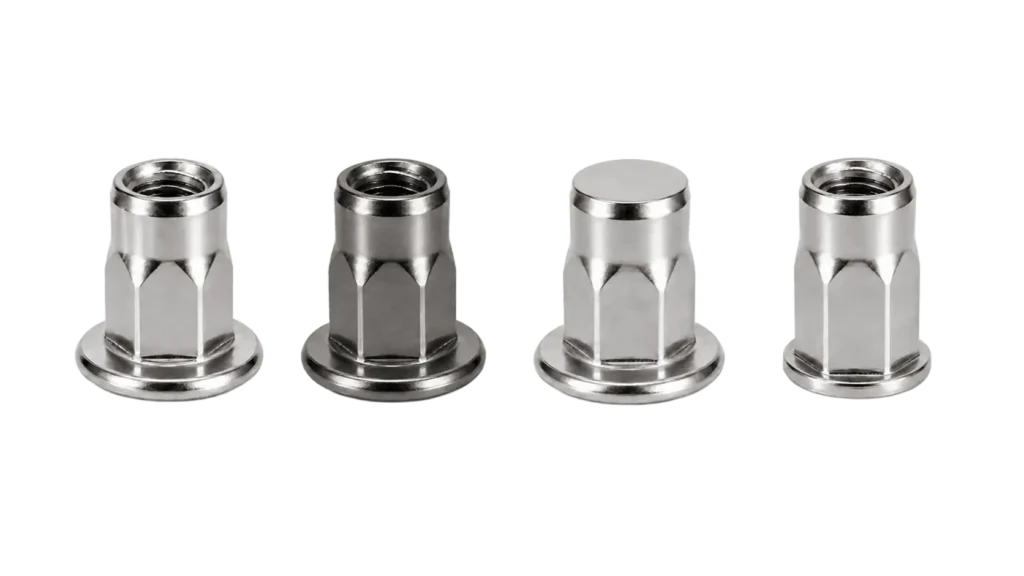
The body features both hexagonal and circular sections. The hexagonal section resists rotation by mating with a matching hole profile. It offers better anti-rotation performance than Knurled Body Rivet Nuts.
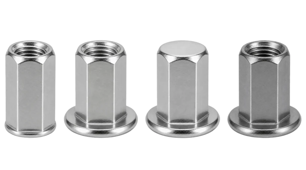
The body has a hexagonal outer contour and requires a matching hexagonal hole for installation. Rotation is restricted by the geometric fit between the hexagonal body and the hole walls. It is suitable for connections with high anti-rotation performance requirements.
How Grip Range and Hole Size Affect the Joint
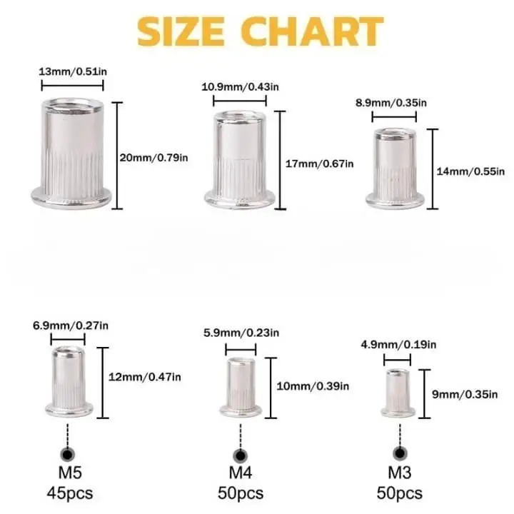
The clamping range determines whether the rivet nut you choose can “properly clamp the sheet metal.” The size of the mounting hole determines whether the rivet nut can “be correctly positioned and reliably transfer the load.”Selecting the appropriate clamping range and mounting hole diameter is key to ensuring that the rivet nut is installed correctly, provides a secure connection, and minimizes the risk of loosening or rotation.
If the actual sheet thickness is below the rivet nut’s clamping range, the rivet nut cannot form a stable clamping state in the correct position. This results in issues such as loosening after riveting, the rivet nut rotating easily when tightening bolts, and sheet deformation. If the actual sheet thickness exceeds the rivet nut’s clamping range, it will lead to insufficient clamping and incomplete deformation on the reverse side.
The size of the mounting hole is also a key parameter in product selection. If the mounting hole is larger than specified, the gap between the body of the rivet nut and the hole wall will increase. After installation, the rivet nut’s performance will be compromised. If the hole diameter is too small, the rivet nut will be difficult to insert; forcing it in may scratch the surface plating of the rivet nut and the coating on the edges of the sheet metal hole. The rivet nut will also be unable to deform sufficiently.
Manual, Pneumatic, and Battery Rivet Nut Tools
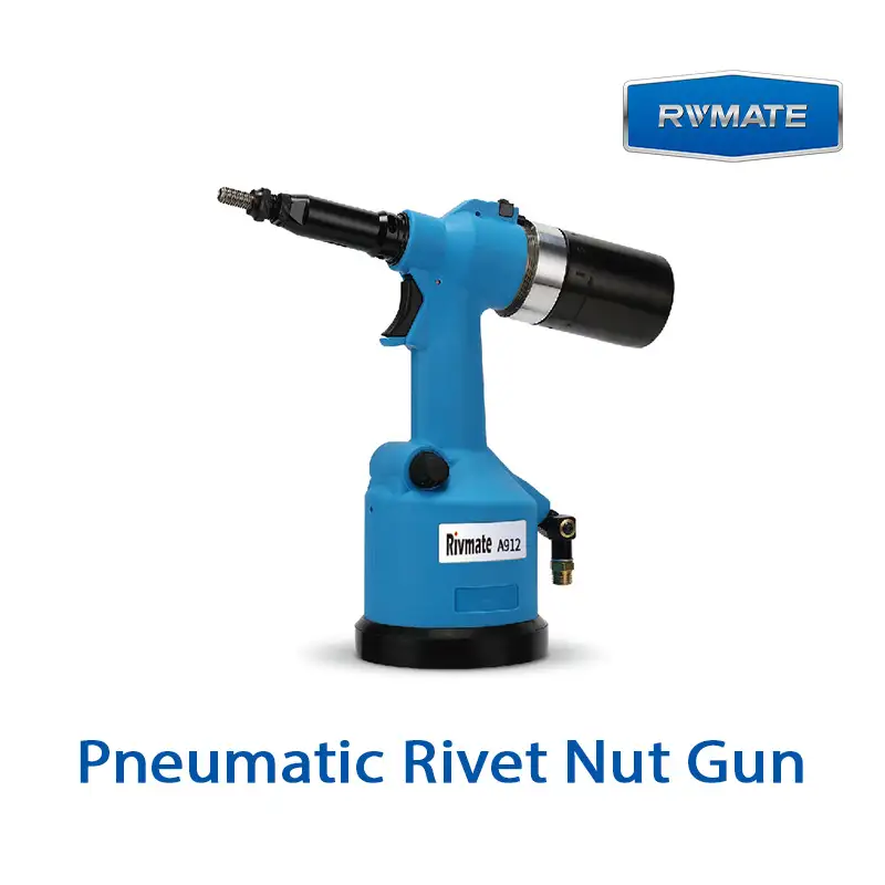
The primary function of a rivet nut tool is to transfer the installation force from the pull rod to the rivet nut, causing it to undergo controlled deformation and clamp the sheet metal. The operating principles of different types of rivet nut tools are largely similar. The differences lie in operational efficiency, installation consistency, portability, applicable sizes, and usage scenarios.
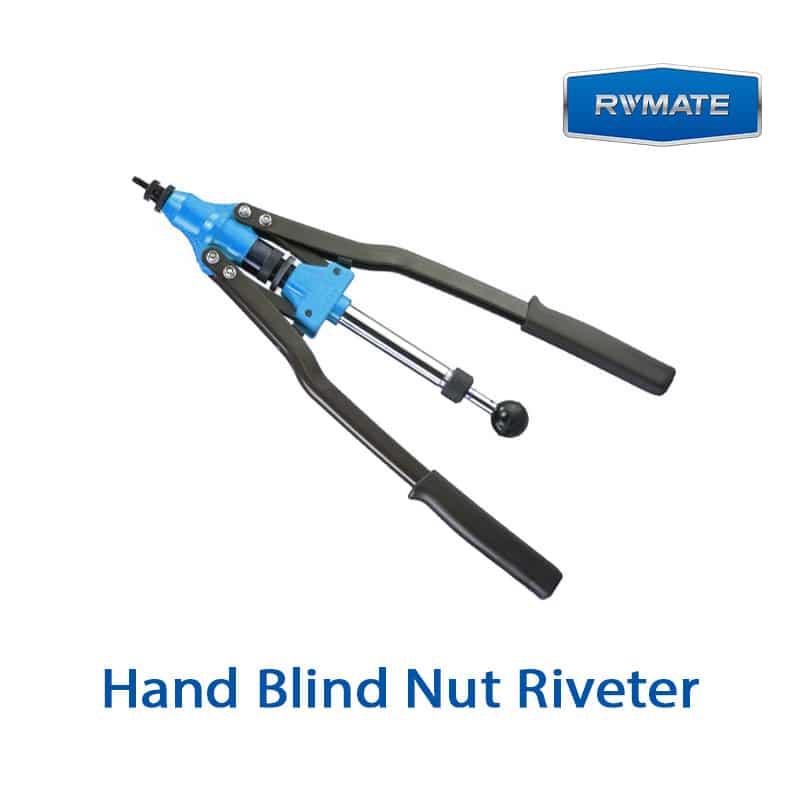
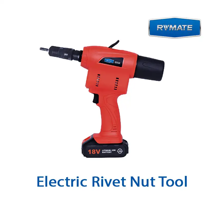
Next, we will take a closer look at the differences between manual, battery-powered , and pneumatic rivet nut tools.
| Comparison | Manual Rivet Nut Tool | Pneumatic Rivet Nut Tool | Battery Rivet Nut Tool |
|---|---|---|---|
| Power Source | Manual hand force and leverage | Compressed air | Battery-powered motor |
| Installation Speed | Lower | High; suitable for continuous installation | Relatively high |
| Installation Consistency | More dependent on the operator | Easier to maintain consistent installation | Easier to maintain consistent installation |
| Portability | Very high; no air supply or battery required | Lower; requires an air hose | High; no air hose required |
| Operator Fatigue | More noticeable during repeated installation | Relatively low | Relatively low, although tool weight must be considered |
| Suitable Installation Volume | Low-volume and occasional installation | High-volume and continuous production | Medium-volume to frequent mobile installation |
| Typical Applications | Repairs, prototypes, and occasional assembly | Production lines and high-volume industrial assembly | Field installation, repair work, and mobile assembly |
| Main Limitation | Lower efficiency and higher effort for larger rivet nuts | Requires a stable compressed-air supply and limits mobility | Battery runtime and tool weight must be considered |
Why Rivet Nuts Spin, Strip, or Set Incorrectly
Rotation, stripped threads, and improper installation are the three most common issues with rivet nuts. While these problems may appear to be caused by the rivet nut not being installed correctly, they are actually due to process mismatches such as plate thickness, hole diameter, tooling, and thread condition.
- Spin” occurs when the entire body of the rivet nut rotates inside the hole while tightening or removing the bolt.
- “Strip” occurs when the internal threads lose proper engagement, preventing the bolt from being securely tightened.
- “Set Incorrectly” refers to a situation where the rivet nut does not achieve a sufficient clamping state. This includes insufficient clamping, incorrect deformation positioning, or excessive deformation.
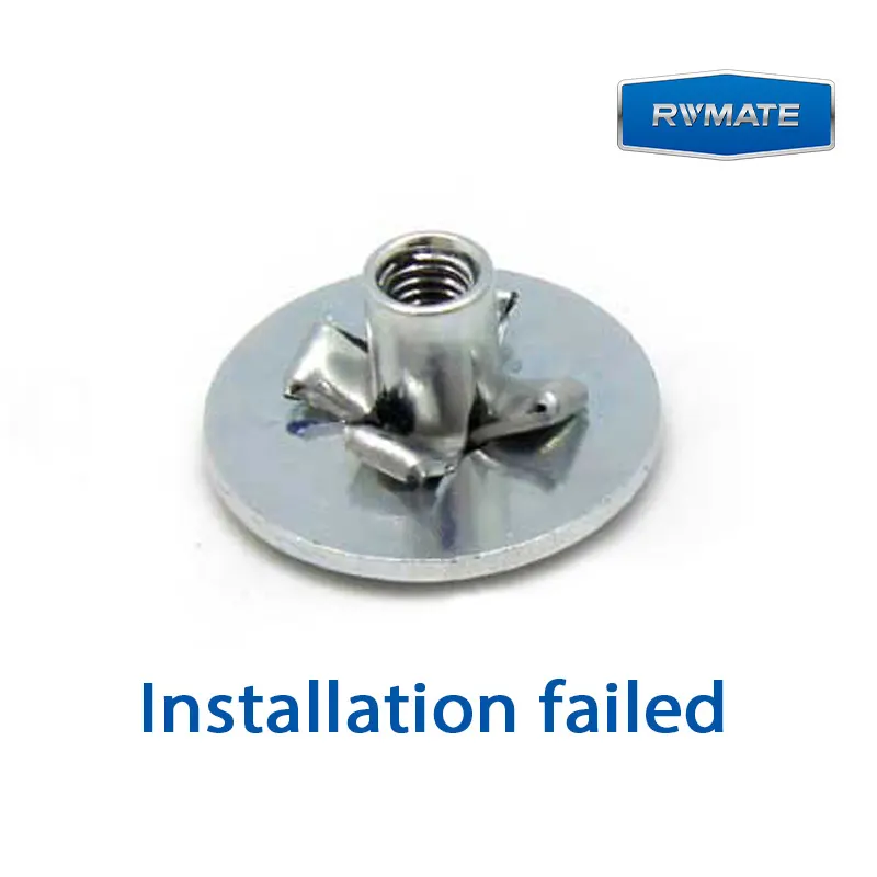
The primary reason rivet nuts rotate is that the hole lacks sufficient resistance to rotation. Resistance to rotation comes from the clamping force after installation, the mechanical interlock between the knurled surface and the hole wall, or the geometric constraints between the hexagonal body and the hexagonal hole.
There are three main reasons why rivet nuts rotate:
- The mounting hole is too large. Increased clearance between the rivet nut and the hole wall makes it easier for the body to rotate inside the hole. For knurled and hex rivet nuts, an oversized mounting hole reduces the effectiveness of geometric anti-rotation.
- Insufficient installation. During installation, if the tool’s installation force or stroke is insufficient, the rivet nut will not deform fully and will be unable to effectively clamp the sheet metal. Although the rivet nut may appear secure to the naked eye, it may rotate along with the bolt once significant torque is applied.
- Incorrect body design selection. If your connection requires high bolt tightening torque but you use a smooth cylindrical design with limited anti-rotation capability, the rivet nut may rotate during subsequent use even if there were no obvious errors during installation.
The fundamental cause of rivet nut stripping is damage to the internal threads.
There are several main causes of rivet nut stripping.
- The first category is a mismatch in thread specifications between the bolt and the rivet nut. The thread diameters may appear similar, but the pitch differs, or metric and imperial specifications are mixed. Initially, the bolt may be able to be screwed in a few turns, but continued tightening will damage the threads.
- The second category is when the bolt is screwed in at an angle. This results in a cross-threaded condition. In this case, the bolt does not follow the correct thread path but instead cuts into the existing threads. Continuing to force the bolt tight with a wrench will eventually destroy the internal threads.
- The third cause is over-installation. If the rivet nut is compressed excessively, the threaded area may be subjected to abnormal stress or deformation, making it difficult to screw the bolt in smoothly after installation; in severe cases, this can result in thread damage.
Common signs of improper rivet nut seating include: the rivet nut head not lying flush against the sheet metal, looseness after installation, incomplete deformation on the back side, abnormal deformation locations, dents in the sheet metal, or damage to the internal threads. These issues primarily result from improper matching between the product, the sheet metal, the hole, and the tool.
- The first thing to check is the clamping range. If the sheet metal is too thin or too thick—exceeding the rivet nut’s normal clamping range—the deformation zone may fail to form the correct clamping structure at the designed location. This creates a risk that the rivet nut will not clamp securely after riveting.
- Next is hole quality. If the hole opening has severe burrs or the hole is deformed, the rivet nut head may fail to seat properly, resulting in uneven force distribution. Consequently, the rivet nut will not deform uniformly.
- Another cause is incorrect tool settings. If the installation force or stroke is too low, the rivet nut may not be fully seated. If the settings are too high, excessive deformation may occur.
- The final issue is improper tool operation. If the tool is noticeably tilted during installation, and the pull rod, rivet nut, and installation hole are not coaxial, the force applied to the rivet nut may be skewed to one side, resulting in asymmetrical deformation.
How to Verify a Correctly Installed Rivet Nut
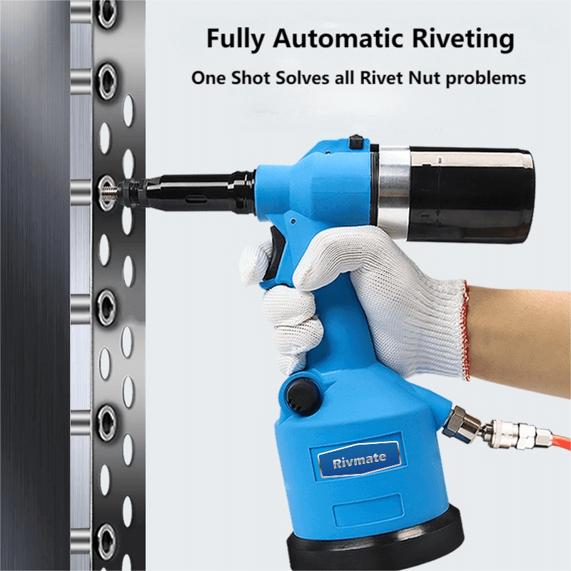
To verify that a rivet nut has been installed correctly, the most reliable method is to inspect the head seating, anti-rotation status, internal threads, back deformation, plate thickness and clamping range, as well as the mounting hole dimensions. Once all these conditions are met, perform anti-rotation or anti-pull-out tests under actual assembly conditions. This is the most conclusive proof of the correctness of the rivet nut connection.
- Step 1.Check whether the head of the rivet nut is properly seated against the sheet metal.
- Step 2. Check whether the rivet nut rotates inside the hole during normal assembly.
- Step 3. Check whether the internal threads are intact.
- Step 4. Check whether the deformation pattern on the back side after riveting is normal.
- Step 5. Check whether the total thickness of the actual material falls within the clamping range specified for this particular model.
- Step 6. Check whether the size and quality of the mounting holes meet product requirements.
- Step 7. Based on the actual connection requirements, use testing equipment to verify the rivet nut’s resistance to rotation and axial pull-out.
FAQs
Do rivet nuts require a special installation tool?
Yes. Rivet nuts require specialized installation tools. These tools ensure that the rivet nut is pulled in correctly and clamped securely. Specialized tools help protect the internal threads of the rivet nut.
Can you install a rivet nut without a rivet nut tool?
Yes. It is suitable for small quantities and installations with minimal requirements. Without a rivet nut tool, it is difficult to control the installation force and stroke, making it impossible to ensure that the rivet nut deforms sufficiently.
How tight should a rivet nut be set?
Yes. It is suitable for small quantities and installations with minimal requirements. Without a rivet nut tool, it is difficult to control the installation force and stroke, making it impossible to ensure that the rivet nut deforms sufficiently.
Why does a rivet nut spin after installation?
There are many reasons why a rivet nut may slip. These include an installation hole that is too large, a clamping range that does not match the plate thickness, and a body design that is not suitable for the required tightening torque.
Does the bolt stay inside the rivet nut during setting?
When installing a rivet nut, the bolt does not need to remain inside the entire time. The bolt is used to secure the parts after the rivet nut has been installed. During installation, it is the tool’s pull rod that remains inside the rivet nut.
Can a rivet nut be installed in a blind hole?
Yes. However, it depends on the structure of the blind hole. For closed square tubes, enclosures, or other structures that can only be accessed from one side, rivet nuts can be used if there is sufficient installation space. Rivet nuts are not suitable for blind holes drilled into solid materials that do not penetrate through the material, because their installation requires a certain amount of space for deformation on the back side.
What happens if a rivet nut is over-set?
Excessive riveting can cause damage to the internal threads, cracks in the rivet nut body, and even separation of the threaded portion from the deformed portion.
Can the same tool install different rivet nut sizes?
Yes. Most rivet nut installation tools support multiple thread sizes. However, you’ll need to replace the corresponding tie rod and support head, and verify that the tool’s installation capacity meets the requirements.
Work with a IATF 16949 Certified Blind Rivet Manufacturer
Get High Quality Rivets Instead of Huck and Avdel Rivets

Rivmate Rivet
Rivmate is blind rivets manufacturers in china. The company is IATF 16949 certified and offers high-strength structural blind rivets that serve as alternatives to Huck and Avdel products.
Explore Rivmate Cases
Rivmate Rivet
Rivmate is blind rivets manufacturers in china. The company is IATF 16949 certified and offers high-strength structural blind rivets that serve as alternatives to Huck and Avdel products.

Hey There, I'm Allen!
I am the boss of Rivmate. For over two decades, we have specialized in the manufacture of blind rivets, providing our customers with reliable riveting solutions. Need riveting services? Feel free to contact us.